Remove existing spindle, Release spindle nut and wheel bolts, Release existing sprocket – Great Plains Gauge Wheel-Spindle User Manual
Page 5
Great Plains Mfg., Inc.
Installation Instructions
5
04/10/2009
195-080M
Remove Existing Spindle
Step 16 through step 91 are for one wing. Start with the
left wing.
Release Spindle Nut and Wheel Bolts
Existing spindle nuts may be difficult to remove due to
exposure to the elements. Loosen them before dis-
mounting wheels.
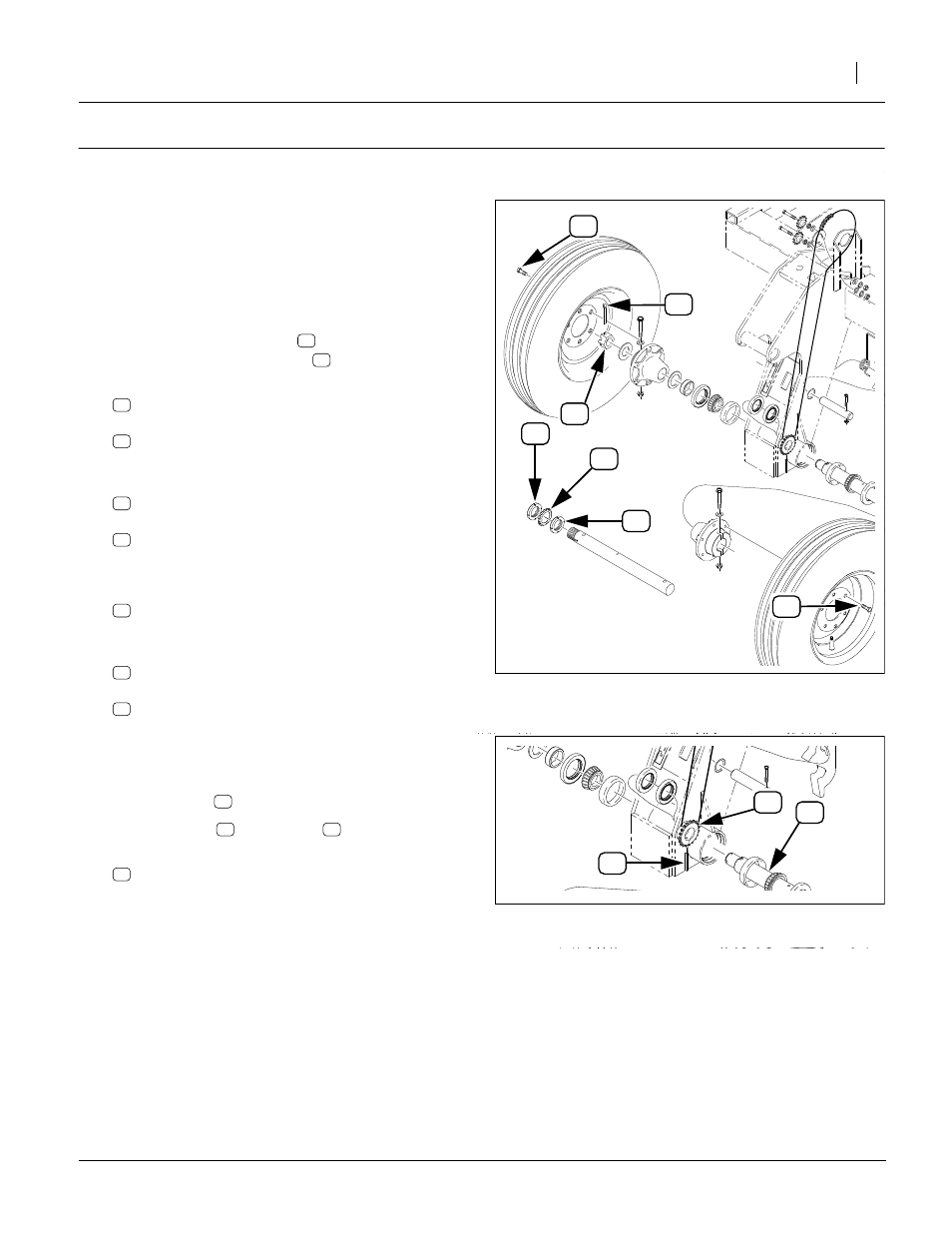
Refer to Figure 4
15. Identify the spindle nut style used on your drill.
For ring-style bearing nuts
For castellated (slotted) nuts
16. At the ground drive, remove the outer:
and
804-098C WASHER BRG LOCK, TW110
These parts are not re-used.
17. Loosen, but do not remove the inner:
and all:
802-104C BOLT WHEEL 1/2-20X1 90-DEG
18. If step 16 and step 17 were done, skip to step 21.
19. At the ground drive, remove one:
805-148C PIN COTTER 3/8 X 3 PLT
The cotter pin is not re-used.
20. Loosen, but do not remove:
803-239C NUT HEX SLOTTED 1 1/2-12 PLT
and all:
802-104C BOLT WHEEL 1/2-20X1 90-DEG
Release Existing Sprocket
Refer to Figure 5
21. Jack up the wing ground drive weldment. Locate the
inner sprocket
inside the lower weldment.
22. Rotate spindle
is accessible.
23. Drive out roll pin:
805-030C PIN ROLL 5/16 X 3 PLT
This pin is not re-used.
Figure 4
Release Existing Spindle Nuts
29445
Figure 5
Release Existing Sprocket
29445