Great Plains YP2425A Material Rate User Manual
Page 26
24
YP2425A
Table of Contents Metric Charts
Great Plains Manufacturing, Inc.
401-626B
Table of Contents Metric Charts
2012-02-29
Refer to Figure 7
6.
At the rear (long mount) row unit of each pair, note
which sprocket tooth is at the index mark
. If the
sprocket is already at the chart value, skip to
step 12. Otherwise, complete step 7 through step 10
for that row.
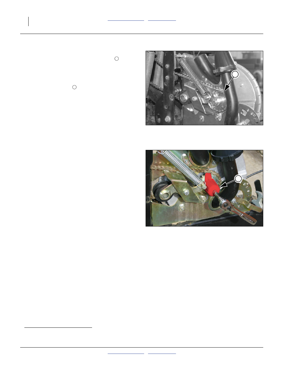
Refer to Figure 8
7.
Place the timing tool
over the meter shaft. Attach
a
3
⁄
8
inch (10 mm) socket wrench to aid in rotation.
Sweep the tool
a
tooth under the chain, rotating in the
direction opposite of that desired for sprocket
adjustment.
Each clockwise rotation of the timing tool advances
the sprocket by one tooth.
Each counter-clockwise rotation of the timing tool
retards the sprocket by one tooth.
8.
Advance or retard the sprocket until the desired tooth
number is at the index mark. Hold the sprocket
stationary, and re-mount the chain, making sure the
chain is taut in the top loop.
9.
Rotate meter shaft backward, or rotate wing drive
shaft forward to tension chain. Re-check that front
row sprocket is still at “1”.
10. Check the position of the rear row sprocket. The
tooth tip at, or just ahead of the index mark must be
the tooth called for by the chart. If not, release spring
and re-mount chain.
11. Repeat step 4 through step 10 for each row pair.
12. Re-install seed discs and meter covers. No particular
disc orientation is required during seed disc
installation. The disc is symmetrical about all four
seat lobes.
a. If the timing tool is not available, remove the idler tensioning spring to adjust the sprocket position. Rotate meter shaft backward (if
meter empty, otherwise forward one full rotation), and re-check indexing with normal tension on chain.
Figure 7
Sprocket Index Check
29628
2
2
3
Figure 8
Adjusting Sprocket Index
31444
3