Marker adjustments, Marker width – Great Plains 2525F Operator Manual User Manual
Page 29
Adjustments 25
01/23/2012
118-232M
Marker Adjustments
Pinch, Crush and Sharp Object Hazards:
You may be injured if hit by a folding or unfolding marker.
Markers may fall quickly and unexpectedly if the hydraulics
fail. Never allow anyone near the drill when folding or unfold-
ing the markers.
There are four operating adjustments for markers:
• Marker Width (Extension)
Once set for a specific row spacing, this only needs
periodic checking to ensure the clamp is secure.
• Disk Angle
Even if your row spacing rarely changes, you may
need to adjust disk angle for soil conditions and plant-
ing speed.
• Chain Length
You may want to adjust the chain length to ensure the
markers track uneven ground, and/or are off the
ground when the drill is raised.
• Marker Speed
Once initially set by your dealer, this rarely needs
modification.
There are also three maintenance items for markers:
• “Marker Cylinder Bleeding” on page 48.
• “Marker Shear Bolt Replacement” on page 49.
• “Marker Transport Carrier” on page 49.
Marker Width
Marker extension depends on drill size, row unit spacing
and row units in use.
See “Marker Extension” on page 63 for initial values for
marker extension.
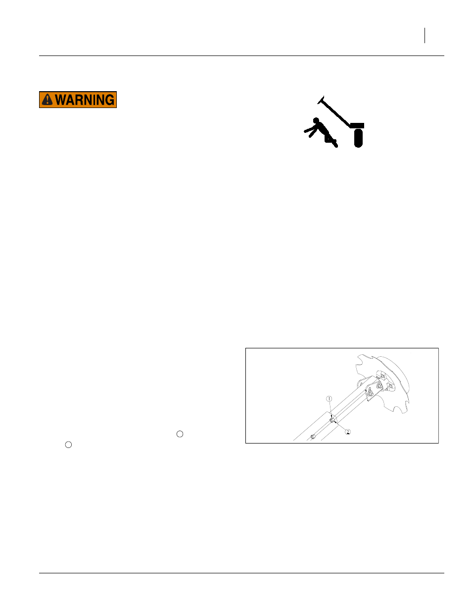
Refer to Figure 22
To adjust marker width, loosen jam nuts
and
1
⁄
2
in set
screws
. Move marker disk tube in or out to get the
proper dimension.
Refer to Figure 73 through Figure 122 beginning on page 63.
The diagrams shows marker width for the different
opener spacings and opener configurations.
To measure for marker width adjustment:
1.
Lower drill in the field and drive forward a few feet.
2.
Measure from the centerline of the outside row unit
(not pair, and whether that row is in use or not) to the
mark in the ground made by the marker disk.
Note: Extension for left and right sides may not be identi-
cal in some drill configurations.
Note: For some row unit configurations, the inner marker
tube is too long. If your adjustment causes it to
interfere with other drill components, cut off just
enough of the excess length to eliminate the inter-
ference.
FigureSpacer
Figure 22
Marker Extension Adjustment
19204
1
2