Valve bracket, Valve mounting, hose & wiring harnesses, Valve & hose assembly – Great Plains 3000TM User Manual
Page 3: Valve mounting, hose & wiring har- nesses
Great Plains Manufacturing, Inc.
3
03/06/2013
586-543M
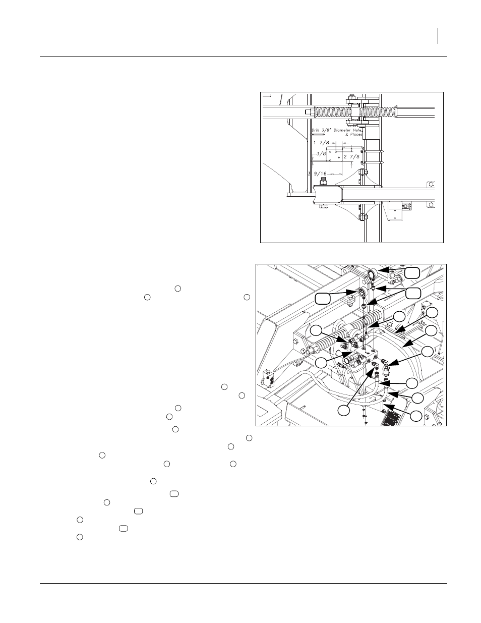
Valve Bracket
Refer to Figure 3
Note: Wings may be un-folded to finish installation. Be sure
pressure is off fold cylinders as hoses will need removed
from valve. You may want to get a bucket to catch some of
the oil when hoses are unhooked.
8.
Two new 3/8” diameter holes will need drilled in locations
shown.
Null4.aac:
Valve Mounting, Hose & Wiring Har-
nesses
Valve & Hose Assembly
Attach the new fixed bypass valve
in orientation shown
to the valve bracket plate
with the 5/16 x 3 hex bolts
,
5/16 lock washers and 5/16 nuts.
10. Tighten bolts to specs, See “Torque Values Chart” on
Note: See “Hydraulic Connector ID” on page 7 for proper fit-
tings installation and torque. Be sure fittings, valve and
hose ends are clean before installing fittings and hoses.
Do not tighten fittings until the hoses are installed so you
can rotate fittings to clear other fittings and hoses.
11. Attach a 3/4mjic 3/4morb elbow and inline filter
from
old bypass valve to the IN port of fixed bypass valve
.
12. Attach the 3/4mjic 3/4morb elbow
to the other three
ports on the fixed bypass valve
.
13. Re-attach the green extend hose
from tractor to the IN
port (with inline filter). Re-attach the green retract hose
from tractor T port, left side of fixed bypass valve
. Re-
attach hose
running from tee, of fold cylinder base end
to R port of fixed bypass valve
. Re-attach hose
run-
ning from tee, of fold cylinder rod end to T port (right
side) of fixed bypass valve
.
14. Attach 9/16morb 1/4fnpt fittings
to top ports of fixed
bypass valve
. Attach 3000psi pressure gauge with
pressure gauge decal
to left, rear port of fixed bypass
valve
and other 3000psi pressure gauge without pres-
sure gauge decal
to right, front port of fixed bypass
valve
. Have both pressure gauges facing towards front
of machine.
15. Tighten all fittings and hoses to specs, See “Hydraulic
Connector ID” on page 7.
FigureSpacer:
FigureSpacer:
l4:
Figure 3
Valve Bracket
43017
FigureSpacer:
FigureSpacer:
Null4:
Figure 4
Valve & Hoses
43016
2
8
1
3
5
9
10
4
5
6
7
11
12
1
2
3
4
1
5
1
7
6
1
9
1
8
1
10
1
11
1
12
1