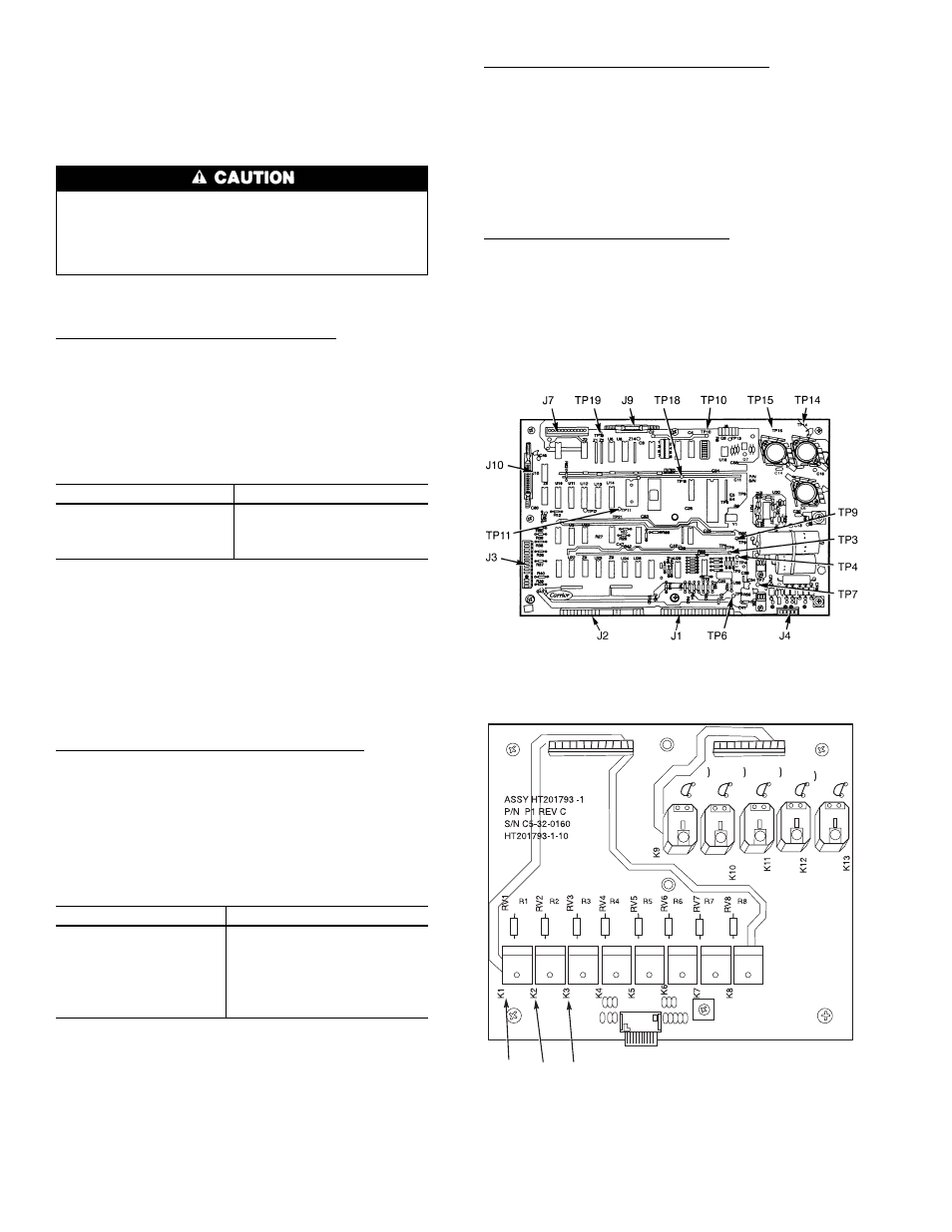
Fig. 48 — processor board test points, Fig. 49 — relay board test points 48 – Carrier 50FK User Manual
Page 48
These 2 steps will help determine if a component other
than a board is at fault or if the problem is external to control
circuit.
A volt-ohmmeter will be needed to troubleshoot boards. A
digital meter is preferred but a Simpson 260 or equivalent
will work.
To prevent damage to solid-state electronic components
on boards, meter probes should only be placed on ter-
minals and test points listed in following sections. Do
not short the electrical components, and use extreme care
while working on the processor board.
PROCESSOR BOARD CHECKOUT — Refer to Fig. 48
and 49 for location of terminal pins and test points.
Step 1 — Check Transformer Input to the Board — Connector
J4 is used to connect the control transformer to the processor
board.
1. Set the volt-ohmmeter to ac voltage with a range setting
of approximately 30 v.
2. Turn control switch to ON position.
3. Check voltage at following terminals on pin terminal con-
nector J4:
TERMINALS
VOLTAGE (AC)
1 to 2
15.3 to 20.9
4 to 6
16.2 to 22.0
5 to 6
8.1 to 11.0
5 to 4
8.1 to 11.0
4. If voltage is not within range, check primary side.
115-v transformer — 104 to 127 vac
230-v transformer — 207 to 254 vac
5. If primary voltage is not correct, check system fuse, trans-
former, ON-OFF switch, and wiring. If these are okay,
contact power company.
6. If primary voltage is correct, but secondary voltage
(24 v ± 10%) is incorrect, replace transformer.
7. Turn control switch to OFF position.
Step 2 — Check Processor Board Power Supply
1. Set meter to approximately 20 vdc.
2. Turn power to OFF position.
3. Connect negative lead to TP18.
4. Turn power switch to ON position and press display but-
ton to enter Quick Test mode.
5. Check voltage between TP18 and each of the following
test pins:
TEST PIN
VOLTAGE (DC)
TP3
ϩ
10
TP4
ϩ
12
TP6
ϩ
5
TP10
ϩ
5
TP14
ϩ
12
TP15
ϩ
12
TP7
−5*
*If not using a digital meter, leads must be reversed.
6. If voltage is incorrect, replace processor board.
7. Turn power to ON position.
Step 3 — Check Voltage Tolerance Circuitry
1. Turn power to OFF position.
2. Negative test probe on TP18 and system in Quick Test
mode.
3. Check voltage TP18 to TP9.
4. If voltage is greater than
ϩ1 vdc, recheck transformer
input voltage.
5. If transformer is okay, replace processor board.
6. Turn power to ON position.
Step 4 — Check Processor Reset Line
1. Turn power to OFF position.
2. Negative probe on TP18.
3. Check voltage TP18 to TP11.
4. If voltage is greater than
ϩ3 vdc, reset power and
recheck.
5. If voltage is still incorrect, replace processor board.
6. Turn power to ON position.
LEGEND
J
— Pin Terminal Strip
TP — Test Pin
Fig. 48 — Processor Board Test Points
K1
K2
K3
C1
C2
C3
C4
C5
C6
C7
C8
CR1
CR2
CR3
CR4
CR5
CR6
CR7
CR8
C27
C15
C14
C26
C25
C24
C23
C22
E3
CR9
CR10
CR11
CR12
CR13
C9
C10
C11
C12
C13
R9
R10
R11
R12
R13
J5
J6
C19
C16
C18
C21
LEGEND
CR — Control Relay
J
— Pin Terminal Strip
K
— Relay
Fig. 49 — Relay Board Test Points
48