Great Plains 3N-4020 Assembly Instructions User Manual
Page 3
2/28/2006
113-777M
Great Plains Mfg., Inc.
3
Installation Instructions
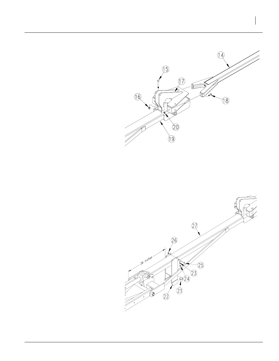
Refer to Figure 4
6.
Assemble third marker section (14) to sec-
ond marker section (19) with 5/8" x 5" bolt
(15) and 5/8" nut lock (16). After the hinge
bolt (15) is installed, take as much play out
of the assembly by tightening both the hinge
bolt (15) and the middle clamp bolt (17).
Stop tightening both bolts when all the play
has been removed. Do not over tighten.
Check to make sure arm (14) can be rotated
by hand. Secure opposite side with 7/16" x
2" bolt (17) and 7/16" nut hex lock (18).
NOTE: The 7/16" bolt (17) is the marker break
away bolt.
Refer to Figure 5
7.
Attach bumper (21) to marker rest bracket
(22) with a 1/2" x 3/4" bolt (23) and 1/2" lock
washer (24).
8.
Attach marker rest bracket (22) to second
marker section (27) with 3/8" x 6" bolts (25)
and 3/8" lock nuts (26).
NOTE: The 34" dimension shown is from the center
of the hinge pin to the inner edge of rest bracket.
20349
Figure 4
Third Marker Section to Second Marker Section
Figure 5
Marker Rest Bracket to Second Marker Section
23204