Assembly instructions – Great Plains 3N-4020 Assembly Instructions User Manual
Page 2
113-777M
2/28/2006
Great Plains Mfg., Inc.
Flat Fold Marker Option
2
Assembly Instructions
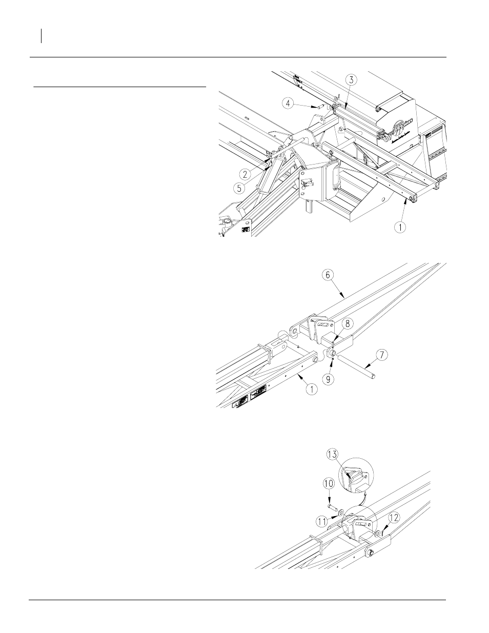
Refer to Figure 1
1.
Lower drill into field position. Allow 25 feet on
each end of drill for marker assembly. Always as-
semble marker in unfolded position.
2.
Mount first marker section (1) on drill frame
mounting bracket using the 1 1/4" x 20 5/8"
marker hinge pin (2). Insert the tapered end of
the pin (2) in first then align the hole on the op-
posite end with the hole in the mounting brack-
et. Secure pin in place with a 5/16" x 2
1/2" bolt and 5/16" lock nut (5).
3.
Attach the base end of the cylinder (3) to the cyl-
inder mount. Mount the cylinder (3) with the hy-
draulic ports facing towards the front of the drill.
Secure cylinder (3) in place with a 1" x 2 3/4" cle-
vis pin (4) and spring clip.
Refer to Figure 2
4.
Assemble second marker section (6) to first
marker section (1) with 20 5/8" hinge pin (7). Fas-
ten with 5/16" x 2 1/4" hex bolt (8) and
5/16" lock nut (9).
Refer to Figure 3
5.
Attach cylinder rod end to second marker
section with clevis pin (10), flat washers (11)
and cotter pin (12).
NOTE: Make sure cylinder pin lock (13) is positioned
under cylinder clevis pin (10).
20347
18924
18924
Figure 1
First Marker Section Assembly
Figure 2
Second Marker Section to First Marker Section
Figure 3
Cylinder Rod End to Second Marker Section