Great Plains ADC1150 Operator Manual User Manual
Page 49
47
Section 4 Adjustments
7/28/10
Model 1150 1995 - 1997 167-058M
Great Plains Mfg., Inc.
Re-engage clutch handle by rotating the handle to
point up. The handle should move towards gearbox
slightly as it is rotated. If resistance is felt use calibra-
tion crank to turn gearbox input shaft while engaging
the clutch, refer to Figure 4-4. This will align the gear
teeth and prevent gear damage. Do not force the
clutch handle into engagement. Make sure that dent-
ent (#1) on the clutch cam surface is engaged with the
roll pin before leaving the gearbox, refer to Figure 4-5.
4.
Set the speed change sprocket orientation as indicat-
ed under the Speed Change Sprocket column in the
Seed Rate Chart.
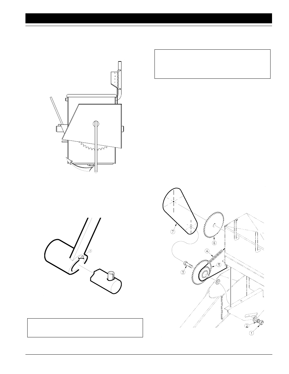
If the speed change sprocket must be changed per-
form the following steps:
Refer to Figure 4-6:
a.
Remove the nut (#1) and washers (#2) from the
bolt holding the sprocket (#5), then remove the
bolt (#3). Note the arrangement of the washers.
b.
Take the sprocket out of the chains and reverse
their position.
c.
Replace the chains onto the correct sprocket.
d.
Position the sprocket at the other end of the slot in
the bracket and replace the bolt. Replace the
washers and nut in the same position as they
were before removal.
e.
Adjust the chain tension if needed, do not over-
tighten. Use the position of the speed change to
adjust the gearbox chain, then adjust the clutch
chain using idlers.
Calibration Crank
Figure 4-4
14477
Cam Detent
Figure 4-5
14475
NOTE: The drill will not meter seed with the clutch
handle disengaged.
NOTE: The speed change sprocket “inner” is con-
nected to the chain from the clutch shaft at the rear of
the chart. The speed change sprocket “outer” is con-
nected to the chain to the gearbox.
Speed Change Sprocket
Figure 4-6
14485