Danger, Spindles, hubs, wheels, & drive chain – Great Plains ADC1150 Operator Manual User Manual
Page 19
17
Section 1 Cart Assembly and Setup
7/28/10
Model 1150 1995 - 1997 167-058M
Great Plains Mfg., Inc.
Spindles, Hubs, Wheels, & Drive Chain
Raise the rear of the cart off the ground high enough to let
the spindles slide into the tubes with hubs attached (the
spindle tube should be approximately 6” above the ground
at lowest point).
!
DANGER!
Crushing hazard. You may be severely injured or killed by the
drill if it falls. Always support the drill securely with jack stands
or blocks before working on unit raised off of the ground.
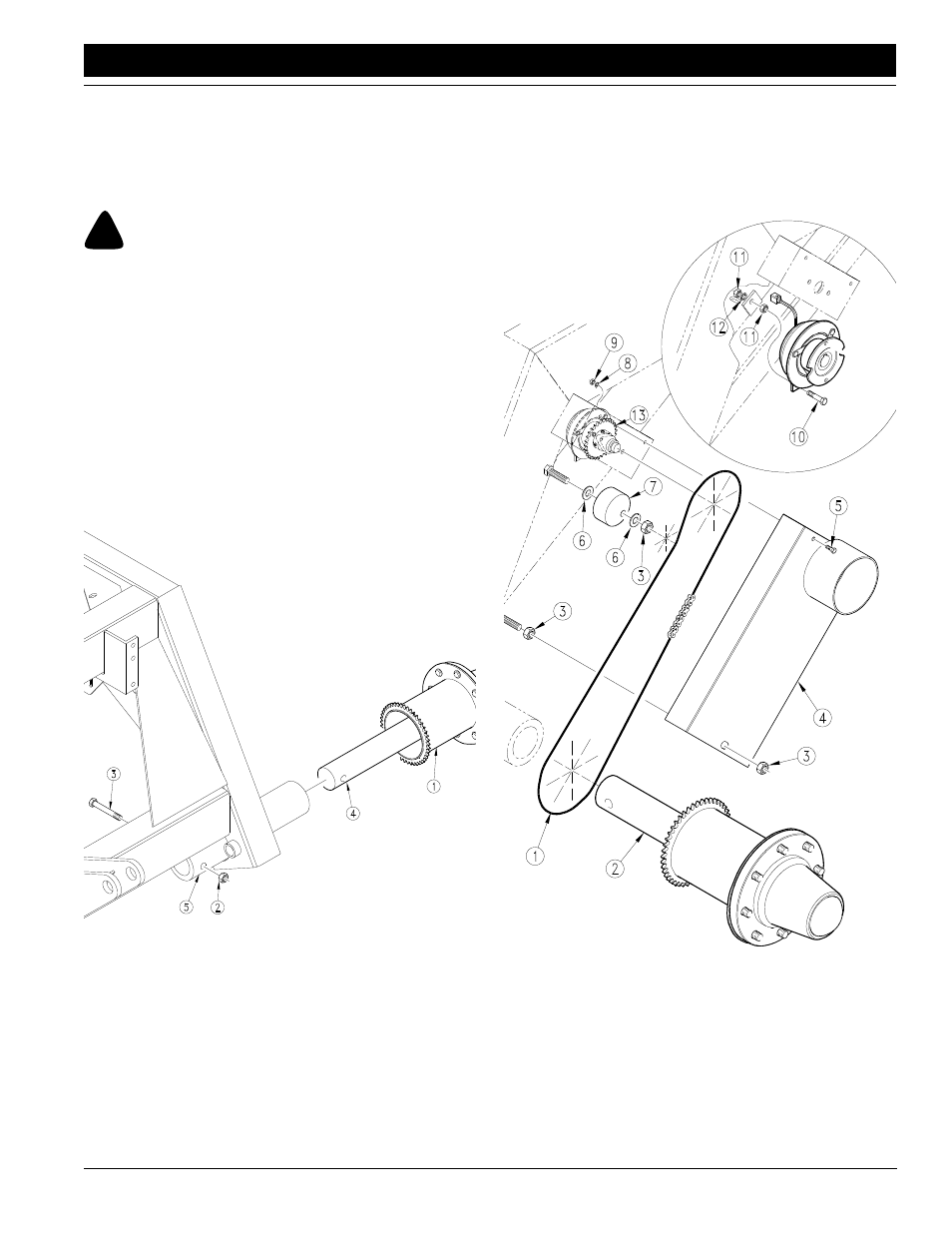
IMPORTANT: Put the hub and spindle assembly with the
drive sprocket on the right side of the drill. Install the as-
sembly without the drive sprocket on the left side of the
drill.
Refer to Figure 1-2 to and line up the bolt hole (#4) in the
hub and spindle assembly with the bolt hole in the spindle
tube (#5). Slide the hub and spindle assembly (#1) into the
tube until the holes are aligned, refer to Figure 1-2. Secure
the hub and spindle assembly in the tube using the 3/4” x
5” long bolt (#3) and the 3/4” lock nut (#2).
Refer to Figure 1-3:
Remove the drive chain mud guard (#5). Loosen the nut
(#7) securing the drive chain tensioner (#9). Turn tension-
er until the thinnest area is toward the front of the drill.
IMPORTANT: Before installing the drive chain make sure
that a 38 tooth sprocket is used on the clutch for the 34’
Spindle Installation
Figure 1-2
14459
implement and that a 29 tooth sprocket is used on the
clutch for the 45’ implement.
Install the main drive chain (#1) on the hub drive sprocket
(#2) and electric clutch sprocket (#16). The chain goes in
front of the drive chain tensioner (#9).
Rotate the drive chain tensioner counterclockwise to re-
move excess chain slack then re-tighten nut (#7) to se-
cure. Check alignment of the chain and sprockets. If
adjustment is needed, loosen the set collars (#1) holding
14436
Main Drive Chain Installation
Figure 1-3