Frame adjustments – Great Plains 3S-4000F Predelivery Manual User Manual
Page 25
9/12/2009
195-242Q
23
Setup
Frame Adjustments
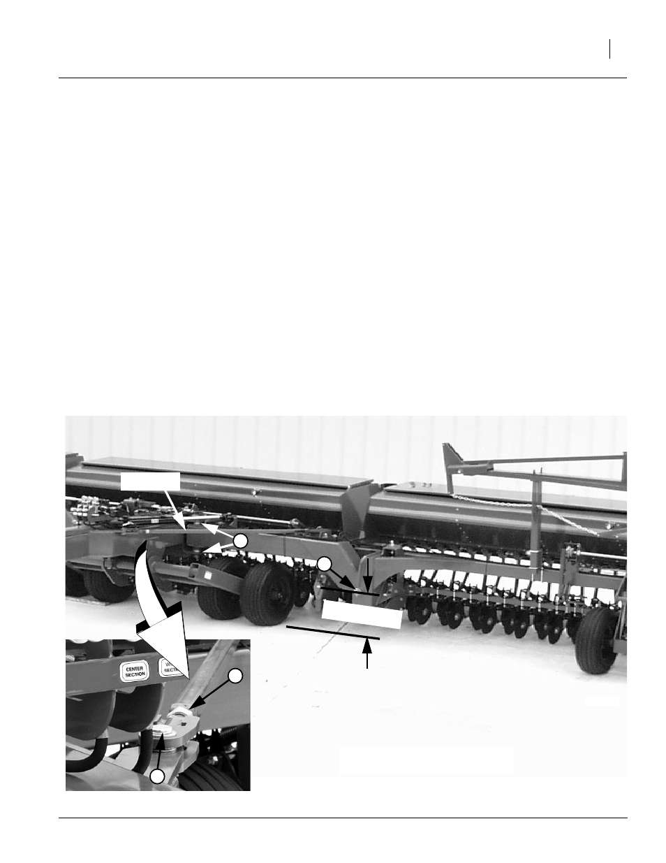
Toolbar Height Adjustment
Toolbar height is factory set and normally will not
require adjustment. If the toolbar is visibly not lev-
el, spacer washers on vertical pivot pins allow for
a small amount of toolbar-height adjustment.
Refer to Figure 7.
To check toolbar height, park drill on a level sur-
face. Measure from ground to horizontal pivot pin
(1). If dimension on either side of drill varies more
than 1/4 inch, adjust toolbar height.
To adjust toolbar height, reposition spacer wash-
ers (2). First lower openers and set enough
opener down pressure to help balance frame.
Raise toolbar by removing spacer washers from
top of the vertical pivot and placing them on bot-
tom side of pivot. Lower toolbar by removing
spacer washers from bottom of vertical pivot and
placing them on top of pivot.
18845
Figure 7
Toolbar and Link Tube Adjustments
1
Link Tube
2
Toolbar Height
4
3
Truss Tube
Refer to Figure 7.
Provide a small amount of tension on truss tube to
help hold draft load from tool bars.