Sensor box adjustments – Great Plains PFH-20 Operator Manual User Manual
Page 15
13
Section 1 Assembly and Setup
6/21/2004
PH-15, PH-20, PFH-15 and PFH-20 Coulter Command System 148-384M
Great Plains Mfg., Inc.
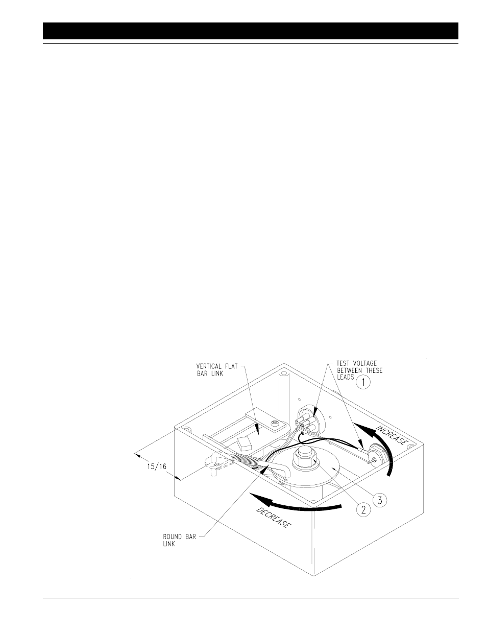
decreases the voltage potential.
2.
The second means of adjusting the linkage inside the
sensor box involves measuring from the inside edge
of the box to the left pivot of the formed round-bar link.
The depth sensing wheel should be off the ground and
rotated down as far as its spring-loaded down-pres-
sure link will allow. Remove the cover from the sensor
box and inspect the internal linkage for proper assem-
bly as shown in Figure 1-10.
With the depth sensing wheel in the max down posi-
tion, the pivot between the vertical flat-bar link and the
formed round-bar link should be 15/16 inch from the
front inside edge of the sensor box.
With the sensor box linkage properly assembled, loos-
en the 3/8 inch hex flange nut on the sensor spindle
and rotate the circular disk until the pivot between the
vertical flat-bar link and the formed round-bar link is
15/16 inch + or - 1/16 inch from the front inside edge of
the box. Be careful not to rotate the circular disk as
you retighten the nut. Replace the sensor box cover.
Once the voltage potential reads 5 volts DC, + or - 1/4
volt, tighten the 3/8 inch flange nut. Be careful not to ro-
tate the circular disk as you tighten the nut. Replace the
sensor box cover.
Some models of the sensor box have a mark on the
vertical flat-bar link which should line up with a mark
on the link’s slotted mount plate at the correct preset
voltage. With the depth sensing wheel in the max
down position, the marks should line up at a voltage of
5 volts DC + or - 1/4 volt. Aligning the marks is more
accurate than relying on the 15/16 inch measurement.
Figure 1-10
Sensor Box Adjustments
12619
Sensor Box Adjustments
Refer to Figure 1-10.
Coulter command depth sensing wheel assemblies which
are preassembled at the factory are preadjusted and
should not require further adjustment. If the sensor box at
the depth sensing wheel has been field installed, or if its
linkage gets out of adjustment, it must be adjusted using
one of the following two procedures:
1.
The best and most accurate means of adjusting the
linkage inside the sensor box makes use of a voltme-
ter which reads 0-12 volts DC. The Control Box in the
tractor must be properly connected to a power source
and the POWER switch must be ON. The TONGUE
HYDRAULICS switch should be in the MANUAL
mode. The wiring harness must be connected to the
control box and the sensor box. The depth sensing
wheel should be off the ground with the arm rotated
down as far as its spring-loaded down-pressure link
will allow. Remove the cover from the sensor box and
inspect the internal linkage for proper assembly as
shown in Figure 1-10.
With the depth sensing wheel in the max down posi-
tion, the voltage potential between the lead containing
the WHITE WIRE and the ground lead (BLACK WIRE)
in the gauge wheel sensor box (#1) should be 5 volts
DC plus or minus 1/4 volt. To adjust the gauge wheel
sensor box linkage, loosen the 3/8 inch hex flange nut
(#2) on the sensor spindle and rotate the circular disk
(#3) until the voltage potential between the lead con-
taining the WHITE WIRE and the ground lead (BLACK
WIRE) (#1) is 5 volts DC plus or minus 1/4 volt. Rotat-
ing the circular disk counterclockwise increases volt-
age potential, and rotating the circular disk clockwise