Great Plains PFH-20 Operator Manual User Manual
Page 12
10
Section 1 Assembly and Setup
PH-15, PH-20, PFH-15 and PFH-20 Coulter Command System 148-384M
6/21/2004
Great Plains Mfg., Inc.
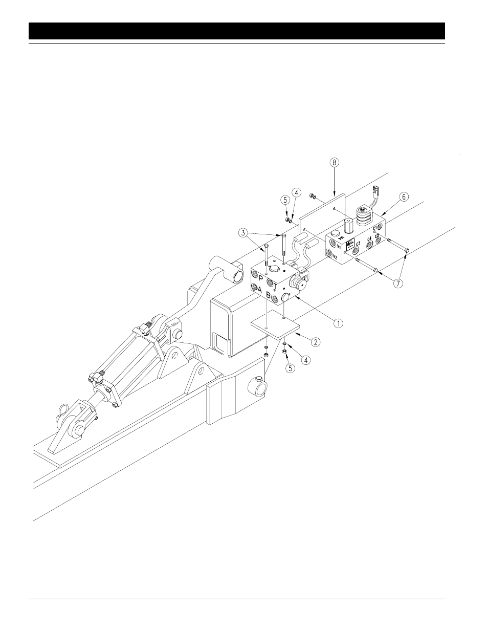
Figure 1-7
Hydraulic Control Valve
19361
Hydraulic Control Valve
Refer to Figure 1-7.
1.
Bolt the electronic depth control valve (1) to the top of
the valve mount bracket (2) with 5/16 x 4 inch bolts (3),
lock washers (4) and hex nuts (5). Position valve so
solenoids set above the middle of the top surface of
valve mount.
2.
Bolt the lift circuit manifold (6) to the side of the valve
mount bracket with 5/16 x 4 inch bolts (7), lock wash-
ers (4) and hex nuts (5). Position valve so the four
ports point away from valve mount and solenoid points
up.
3.
Attach the valve mount to the Precision Hitch with 1/2
x 5 1/2 inch bolt (8), lock washer (9) and hex nut (10).
Assemble the bolt through the pivot tube (11) located
behind the tongue cylinder. Position valve mount so
dual solenoids face toward rear of machine.