Great Plains 30-Foot 3-Section Vintage Drill User Manual
Page 8
4/8/04
1-6
113-368M
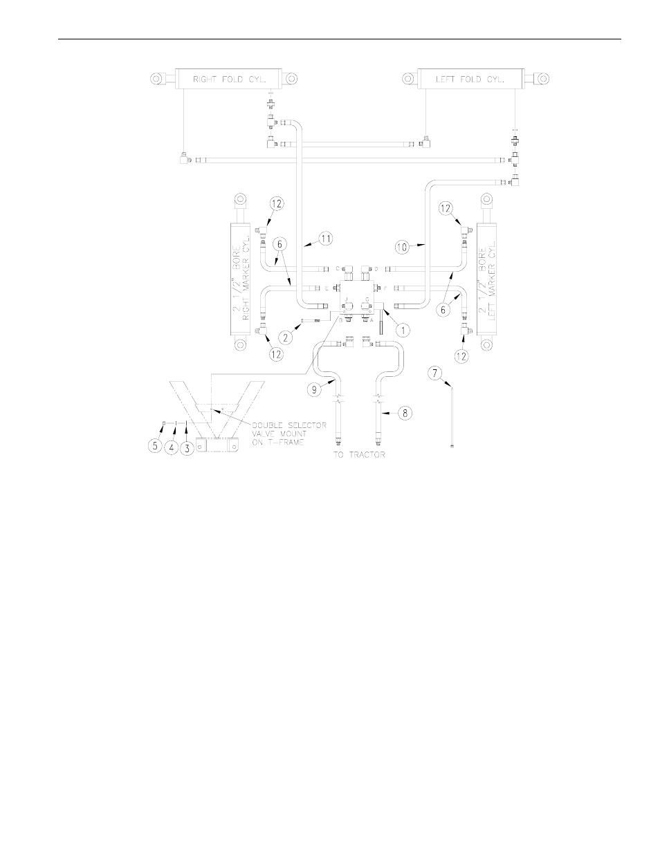
DUAL FLAT FOLD MARKER ASSEMBLY INSTRUCTIONS
Refer to Fig. 2 as reference for the following instructions:
1.
Attach the hydraulic fittings (#12) to the marker cylinder.
2.
Install the selector/sequence valve to the selector valve mount, located on the T-Frame, using 3/
8" bolts (#2), flat washers (#3), lock washers (#4), and hex nuts (#5).
3.
Route hoses (#6) from the selector/sequence valve down the transport frame tube. Check hose
routing for pinching and kinking of hoses and securely attach with plastic cable ties (#7).
4.
Attach hoses to cylinder ports. Be certain to double check for correct port location back to the
sequence valve.
5.
Detach existing tractor hoses, (#8) and (#9), from fold cylinders. Attach 66" hose (#10), 42" hose
(#11), and tractor hoses, (#8) and (#9), to the selector/sequence valve (#1) and fold cylinders. Assem-
ble remaining hoses as indicated.
6.
Cycle attached marker to transport position with the cylinder closed. Sequence valve should shift
and activate the other cylinder. Refer to page
1-7 for proper cycle sequence.
7.
When ready to fold wing boxes for transporting, position the handle on the selector/sequence valve
towards the port marked "G". Hydraulic oil is now diverted to the fold cylinders.
Fig. 2
10059