Ram extension installation, On auger axle frame (figure, In figure 3.10 using the bo – Wheatheart Self-Propelled Auger Kit (Competitors Models) User Manual
Page 22
3. A
SSEMBLY
W
HEATHEART
- S
ELF
-P
ROPELLED
A
UGER
K
IT
3.9. R
AM
E
XTENSION
I
NSTALLATION
C
OMPETITOR
M
ODELS
22
30766 R0
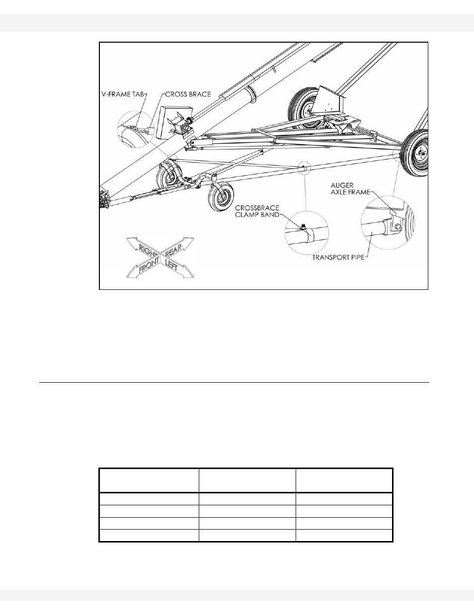
Figure 3.10 Self-Propelled Auger Frame Installation
12. One end of the crossbrace is attached to the v-frame tab, the other is
attached to the transport tube using clamp bands (Figure 3.10).
13. When attaching to the v-frame, be sure to mount one crossbrace to the top
side of the v-frame tab, and the other to the bottom.
3.9. RAM EXTENSION INSTALLATION
The ram extension slides into the a-frame attached to the tabs on the v-frame.
The ram extension length must be set at the proper distance from the ram
mounting a-frame for proper operation of the transport kit (see Table 3.1 and
Figure 3.11 (measurement “X”)).
Table 3.1 Recommended Transport Pipe Length
Auger Tube Length (ft)
Ram Extension
Length
Transport Pipe
Length
30’-36’
6”-20”
76”
35’-41’
7”-23”
86”
40’-46’
8”-27”
101”
47’-60’
14”-38”
120”