Wheatheart Self-Propelled Auger Kit (Competitors Models) User Manual
Page 21
W
HEATHEART
- S
ELF
-P
ROPELLED
A
UGER
K
IT
3. A
SSEMBLY
C
OMPETITOR
M
ODELS
3.8. U
NDERCARRIAGE
I
NSTALLATION
30766 R0
21
3. Make sure that tabs are square to axle and oriented straight down.
4. Attach
transport
frame
pipes to axle tabs on the auger axle frame as shown
in Figure 3.10 using the bolts and locknuts provided.
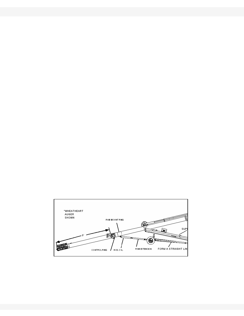
5. In the location noted in Figure 3.9, bolt the control panel ring to the auger
tube approximately 9’ from the intake cage. Do not tighten the bolts yet.
Note:
The hydraulic ram is normally mounted to a separate ram mount ring, not the
control ring (Figure 3.9). The only exception to this is if the straight line path from
the axle to the tube intersects the control ring.
6. Mount the ram mount ring to the tube as indicated ahead of the control ring;
7. Connect the fully retracted cylinder to the tab on the ram mount ring and the
ram extension.
8. The ram extension slides into the a-frame attached to the tabs on the v-frame
as shown in Figure 3.11. The ram extension length must be set at the proper
distance from the ram mounting a-frame for proper operation of the transport
kit. To set the ram extension length, elevate the v-frame to adequately clear
the ground, but not interfere with the auger support arms.
9. Elevate
the
v-frame,
undercarriage pipes, and ram assembly to form a
straight line (transport position) as shown in Figure 3.9. Tighten the control
ring and ram mount ring bolts.
10. If the frame components prevent the transport frame pipes from forming a
straight line, then the frame pipes and axle tabs must be mounted on the
auger support arms. To do this, slide the ram mount ring, cylinder, ram
extension, and frame pipes toward the hopper until they form a straight line
and can be attached to the support arms. The transport frame pipes should
not have to be moved more than 2’ in most circumstances.
11. Make sure that the tabs are square and oriented straight down before final
welding.
Figure 3.9 Control Ring Installation