Electric motor installation / alignment – Wheatheart Galvanized Utility Auger User Manual
Page 17
W
HEATHEART
- G
RAIN
A
UGERS
3. A
SSEMBLY
U
TILITY
3.7. E
LECTRIC
M
OTOR
I
NSTALLATION
/ A
LIGNMENT
30644 R1
17
3.7. ELECTRIC MOTOR INSTALLATION / ALIGNMENT
1. Place electric motor (see Table 3.2 for proper horsepower requirements) onto
motor mount and secure. Ensure that motor shaft is parallel to and centered
on discharge tube. Tighten adjust bolt.
2. Slide drive pulley onto motor shaft (see Table 3.1 for suggested sizes). Insert
the appropriate size of square key. Do not tighten set screw until belts are
aligned.
3. Place belts on pulleys. Adjust the 5/8” adjust bolt on front mount plate until
the belts have the proper tension with about a 1/8” deflection.
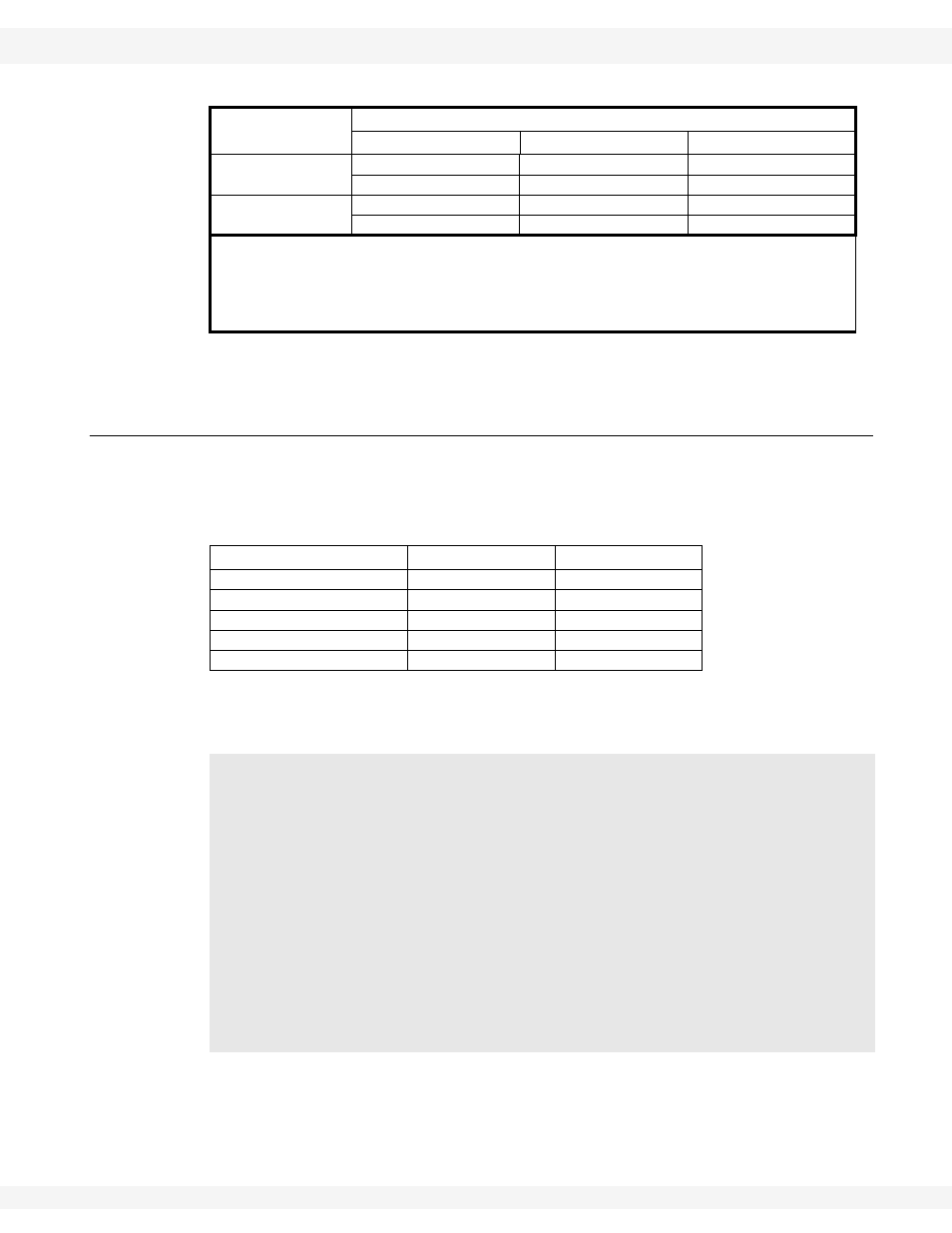
Table 3.1 Pulley Sizes / Combinations
a
Galvanized
Utility Auger
Recommended Sizes
Auger Pulley
Motor Pulley
*Flight Speed (rpm)
8" Utility
12.7”
3 -1/4”
440
12.7”
3 -1/2”
475
10" Utility
15”
3 -1/4”
375
15”
3 -1/2”
402
To determine flight speed (rpm):
b
Divide the speed (rpm) of the motor by the outside diameter of the large auger
pulley, then multiply by the outside diameter of the small motor pulley.
Example: 1725 (rpm) ÷ 15" x 3.5" = 402 rpm
a. Speed calculated using a 1725 rpm electric motor.
b. If a slower flight speed is desired, install a smaller motor pulley.
Table 3.2 Horsepower Requirements
a
a. Approximate electric motor horsepower requirements under normal
conditions. When augering full tube of high moisture grain, addi-
tional horsepower will be needed.
Length
8”
10”
16'-21’
3
3-5
26'-31’
5
5 - 7-1/2
36'-41’
5 - 7-1/2
7-1/2 - 10
46'-51’
7-1/2 - 10
10-15
56'-61’
10
15-20
When using an electric motor:
• The motor and controls should be installed by a qualified electrician in
accordance with all local and national codes.
• Incorporate a magnetic starter to protect the motor.
• The motor must have a manual reset button.
• Locate reset and starter controls so that the operator has full view of the
entire operation.
• Locate main power disconnect switch within reach from ground level to
permit ready access in case of an emergency.
• A main power disconnect switch capable of being locked (in the off posi-
tion only) must be provided.