Motor mount, Powerhead drive, Motor mount 3.6. powerhead drive – Wheatheart Galvanized Utility Auger User Manual
Page 16
3. A
SSEMBLY
W
HEATHEART
- G
RAIN
A
UGERS
3.5. M
OTOR
M
OUNT
U
TILITY
16
30644 R1
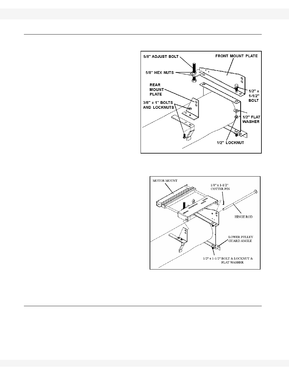
3.5. MOTOR MOUNT
See Figure 3.6 and 3.7.
1. Install
front mount plate
onto head plate of
powerhead using two 1/2”
x 1-1/2” bolts, locknuts,
and 1/2” flat washers
(Figure 3.6). Tighten
securely.
2. Place 5/8” adjust bolt
through available hole in
front mount plate and
secure in place using two
5/8” hex nuts (one top,
one bottom). Leave adjust
bolt loose to allow for later
adjustment.
Note:
The 5/8” nuts and adjust bolt are used to adjust belt tension (Section 3.7.).
3. Assemble rear mount plate
onto tube bracket (Figure
3.6) with two 3/8” x 1" bolts
and locknuts; tighten
securely.
4. Place
motor
mount assembly
in between the two mount
plates and insert hinge rod
(Figure 3.7). Secure hinge
rod with a 1/8” x 1-1/2” cotter
pin.
5. Attach lower pulley guard
angle to the head plate with
two 1/2” x 1-1/2” bolts and
locknuts and 1/2” flat
washers (Figure 3.7).
Tighten securely.
3.6. POWERHEAD DRIVE
1. Remove dirt from upper end of flight shaft.
2. Install the woodruff key provided (or square key), slide the larger pulley onto
the flight shaft with the hub facing away from the auger and do not tighten set
screws at this time (see Table 3.1 for proper pulley size).
Figure 3.6
Figure 3.7