0 throughput – Monarch Instrument ACT-3 User Manual
Page 13
8
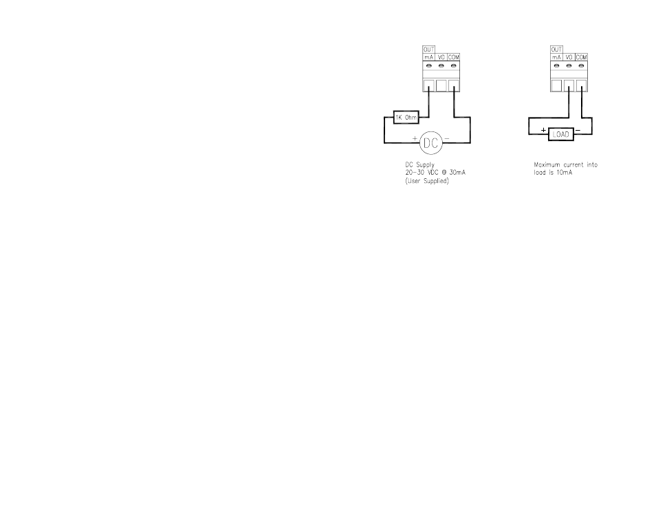
Figure 5 Current and Analog Output Connections
3.0
THROUGHPUT
Throughput is a measure of how fast the instrument processes data. The rate at which the instrument
acquires data is a function of the “Gate Time” and the input frequency. The instrument gets a start
pulse then it continues to get pulses until the Gate Time elapses. The next pulse ends this measurement
and starts the next. At frequencies slower than the Gate Time, the update rate is equal to the period of
the input frequency. Eventually, the instrument has to make the decision that the input is zero, because
theoretically it could wait forever for the next pulse. This Low-End timeout is programmable.
3.1
Display Update Rate
Although the instrument can sample can update up to 244 times a second, to display the data at
this rate would result in a totally erratic display. Therefore, the instrument limits the display
update rate to once every ½ second. Obviously if the input pulses are spaced more than ½ second
apart, the instrument will not have any new data until the next pulse comes along, and the time to
update will be greater than ½ second. The point at which the update rate becomes longer than
every ½ second is when the period of the input (time between pulses) is greater than ½ second,
which is 2 Hz or 120 RPM. Thus, for an input greater than 2 Hz or 120 RPM, the update rate is
twice a second.
For very fast inputs, the unit averages the readings between display updates so that the value
displayed is an average of the total number of acquisitions since the last update.
3.2
Internal Update Rate
The rate at which the limits are checked, the analog output is updated, and the minimum and
maximum are updated, is at the maximum rate at which the instrument acquires data. This is set
by the GATE menu item. The Gate Time can be set to 32.786 mSecs (STD) or 4.096 mSecs
(FAST). See Section 6.14 for more details.
The STD setting is slower (up to 31 readings per second ) but gives more accurate readings
especially for the max and min. Below 31 Hz or 1860 RPM, the internal update rate is the period
of the input frequency. Thus, the response of the alarms, etc can be seen to be a function of the
Current (IO) Output
4 to 20 mA
Analog (AO) Output
0 to 5 Vdc
15
The messages are sent as standard ASCII and all messages end with a carriage return
is no Line feed sent. However, most terminals, printers and computers have the ability to
automatically add a Line feed to a carriage return.
LS1
LIMIT 1 has tripped
LS2
LIMIT 2 has tripped
LR1
LIMIT 1 has reset
LR2
LIMIT 2 has reset
LR3
Both Limits have been forced to reset (RESET button pressed)
UM1
User has entered Menu Mode from front panel
UM2
User has entered Limit Set Mode from front panel
If the user sends a Send display Data (@D1) command, the front panel display value is transmitted
at the display update rate (Refer to Section 3.1). This data always consists of seven characters
including the decimal point. The value 10 will be sent as 10.0000 irrespective of the display mode
of the instrument. This effectively gives a full 6 digits of resolution as opposed to the five on the
display.
8.2
RS232C Commands
The instrument responds to a number of commands sent to its RS232C port. The unit will only
accept data when its Clear to Send Line (Pin 7) is active (positive). All commands begin with @,
end with a carriage return
second is a numeric character. All illegal data is ignored.
There are basically two groups of commands. The first group are Run Mode commands and to
not affect the operation of the unit, other than the execution of the command. The second group
is Control commands and requires further information from the operator.
NOTE: Control commands suspend operation of the instrument until completed.
8.3
Run Mode Commands
These commands do not interfere with the operation of the instrument. They result in an action
only. All commands are activated after the carriage return
entered are not echoed back to the user. However, the results, if any, are sent back to the user.
The following are valid Run Mode commands. Enter the command and then
Command
Action
Response
@R1
Reset LIMIT 1
Unit sends LR1 when done
@R2
Reset LIMIT 2
Unit sends LR2 when done
@R3
Reset both Limits
Unit sends LR3 when done
@R4
Reset Total (and Limits)
Unit sends LR3 when done
Only works when in Total mode
@D0
Sent current displayed value
Unit sends current displayed value once
@D1
Send display data
Unit sends display data until @D2
command
@D2
Stop sending display data
Unit stops sending display data
@D3
Send last calculated reading
This value is changed as fast as the
throughput of the ACT unlike the @D0
command that gives the last displayed value
which only changes up to 2 times per
second. In the Rate of Change (ROC) mode
this command will give the last RPM
measured. To get the displayed ROC value,
use the @D0 or @D1 commands.