Carrier MINIMUM LOAD CONTROL ACCESSORY 30RB060-390 User Manual
Page 3
3
.
6. Dehydrate and recharge each circuit.
7. Restore power to the unit.
NOTE: When piping is completed, leak test the assembly.
Then evacuate, dehydrate, and recharge the circuit using
approved refrigeration practices. Be sure to use the correct
type and amount of refrigerant listed in the nameplate data
and base unit documentation.
Install Control Wiring (See Fig. 6 and 7)
1. One control wire harness is supplied per circuit.
Secure the DIN connector end on the solenoid valve
coil with the screw in the connector. Verify the square
rubber gasket is in place to ensure connection remains
watertight.
2. Route the other end of the cable to the main control panel
(where the display is located). For the circuit A solenoid,
connect leads to TB5-7 and TB5-13. For the B circuit
solenoid, connect leads to TB5-8 and TB5-13. For the
C circuit solenoid (30RB210-300 only), connect the leads
to TB5-6 and TB5-13. In all cases the black wire from the
solenoid must be connected to TB5-13 to ensure correct
polarity. Incorrect polarity will damage the control
boards.
3. For 30RB250-300 units only, locate fan board 3 (FB3) in
the C circuit power control panel. Route the C circuit
solenoid cable to the panel. Locate the orange and brown
wires from channel 7 of connector J3 on this board.
Connect the red wire from the solenoid to the orange wire
from the board. Connect the black wire from the solenoid
to the brown wire from the board.
Configure Unit for Minimum Load Control —
The control must be configured for the minimum load control
operation. Use the scrolling marquee display to configure the
system.
1. Set the Enable/Off/Remote switch to OFF position.
2. Press
until the screen is blank and use the
arrow key to select the Configuration mode LED (light
emitting diode).
3. Press
, then use arrow key to select the
sub-mode ‘UNIT’, then press Enter key.
4. Press the down arrow key until ‘HGBP’ is displayed.
5. Press
key twice. The word ‘PASS’ and
‘WORD’ will flash.
6. Press 0 1 1 1 then
key so that ‘0’ flashes.
7. Use arrow keys to change value to one of the following
configurations:
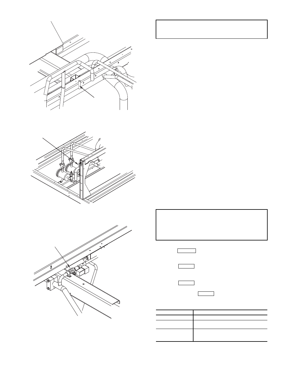
DISCHARGE STUB
Fig. 2 — Typical Stub Tube View
COOLER STUB
Fig. 3 — Stub Tube for Circuit A of Size 110
BALL VALVE
Fig. 4 — Typical View of
5
/
8
in. Swage Tube,
5
/
8
in. Clamp and Solenoid Valve Installed
IMPORTANT: The valve is direction specific and must
have the arrow pointing toward the cooler. The solenoid
valve will not properly seat if installed backwards.
IMPORTANT: This accessory can only be used on units
configured for Cooler Fluid Type (Configuration
SERV
FLUD = 1 [Water]). The minimum load control
accessory (HGBP) is not allowed on units configured for
Cooler Fluid Type (Configuration
SERV
FLUD = 2
[Brine]).
CONFIGURATION
DESCRIPTION
1
Used during chiller start-up only
2
Used during start-up and for close
control of leaving fluid temperature
3
Used during start-up, for close control
of the leaving fluid temperature and for
high ambient unloading
ESCAPE
ENTER
ENTER
ENTER