Turn switch to “on” position – LaMotte Air Pollution Sampling & Measurement User Manual
Page 8
2.
Fill the impinging tube to the designated line with the absorbing
solution. Insert stopper assembly, thereby immersing the long tube
into the absorbing solution. Attach one end of the flexible tubing to
the pump intake fitting. The other end of the tubing is attached to
the short outlet tube of the General Purpose Impinger (0922)
(Diagram 1). The outlet connection draws air from above the liquid
in the impinger chamber. DO NOT connect to the inlet tube of the
impinger which is below the surface of liquid. Check to insure all
connections are tight and that the tubing is correctly connected to
the impinging tube before operating the pump.
3.
Turn switch to “ON” position.
4.
Adjust flowmeter to sample at the designated rate (according to
instructions of testing unit). Turn knob clockwise to reduce flow,
counterclockwise to increase flow. Do not unscrew or withdraw valve
stem beyond threaded section except for maintenance. The
flowmeter is read by aligning the reader’s eye with the center of the
black indicator float and the scale. Graduations on the scale are in
0.1 Lpm increments.
8
Air Pollution Sampling & Measurement
S
24
40
S
24
40
30ML
25
20
15
10
5
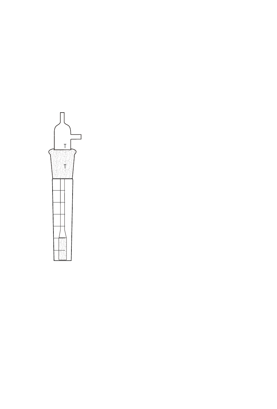
Outlet Tube
Intake Tube
Gas Bubbler
Impinger (0934)
Diagram 2
NOTE: Several air sampling kits use
the Gas Bubbler Impinger (0934)
instead of the General Purpose
Impinger (Diagram 2). In Step 2, the
flexible tubing from the pump is
attached to the side outlet of the
impinger. This is a tight connection
which requires some care and patience
to make. The outlet connection draws
air from above the liquid in the
impinger chamber.