Exide Technologies Section 92.80 User Manual
Page 13
HANDLING AND STACKING HORIZONTAL MODULES
Figure 13
HARDWARE INSTALLATION SEQUENCE
Figure 14
INSTALLING
COMPLETED
HARDWARE
HORIZONTAL STACK
Figure 15
Figure 16
8.3
Horizontal-Multiple Stacks
8.3.1 Stacking Base Modules
It is recommended that all of the first modules with bottom sup-
ports attached (see Section 8.1.1) be placed in position first. A
chalk line floor mark should be used to assure all stacks will be
in a straight line. This applies for stacks end-to-end or end-to-end
and back-to-back. Refer to Sections 6.5 and 8.1.3 for handling
and tip over procedures.
For stacks end-to-end, module ends should be butted together
so that module side channel ends meet (see Figure 17).
POSITIONING HORIZONTAL BASE MODULES
Figure 17
For stacks back-to-back, the two base modules are positioned to
provide a minimum 4.5” spacing between the bottoms of the
modules (not I-beam edges). Refer back to Figure 1.
Refer to layout/wiring diagram for seismic shim requirements.
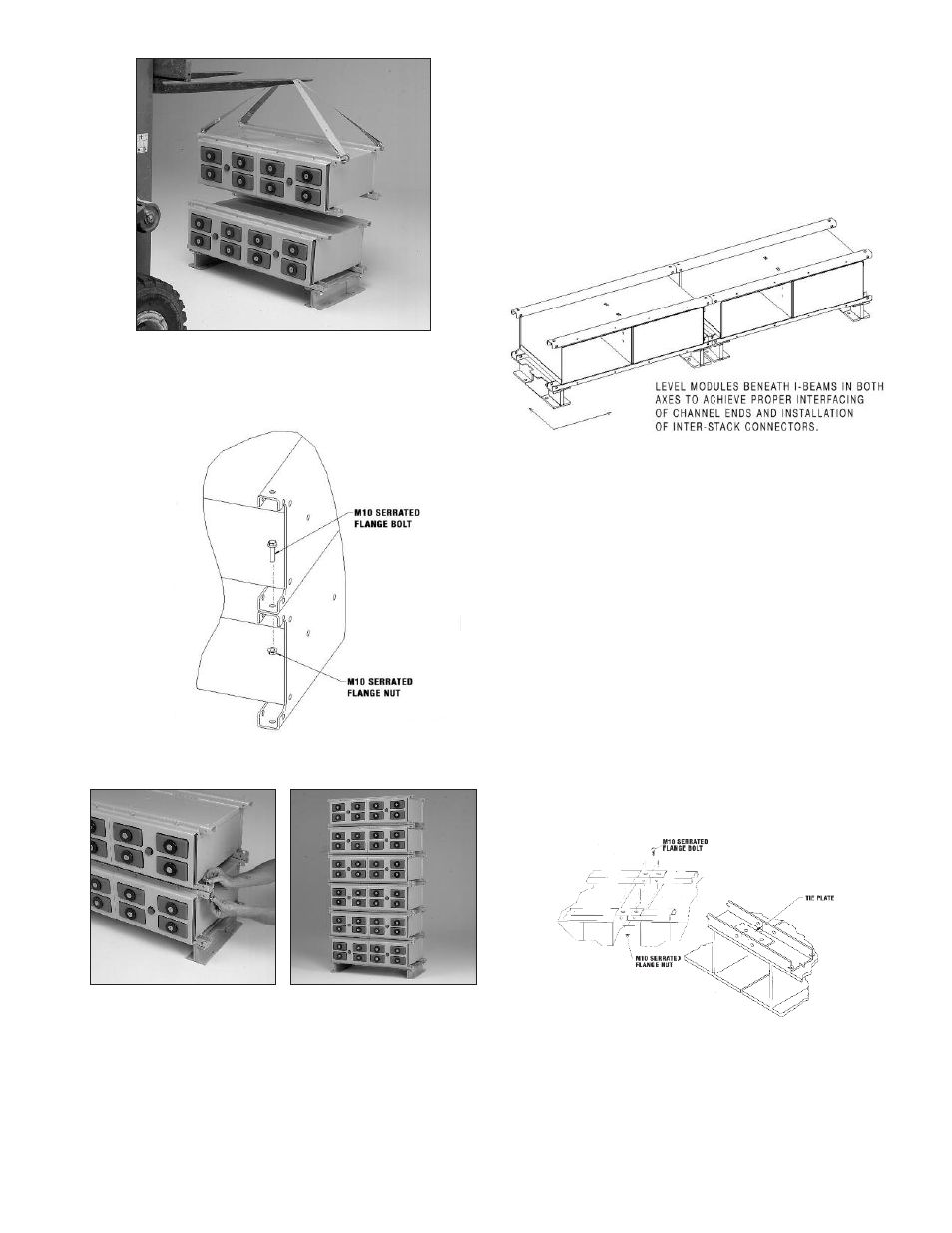
8.3.2 Stack Tie Plates
At this time stack tie plates should be installed. It will be neces-
sary to temporarily remove the hardware fastening the base
modules to the I-beams. To achieve maximum stack stability,
especially where seismic conditions may exist, as well as prop-
er interfacing of inter-stack connections, metal tie plates are pro-
vided. The plates used on stacks end to end are 3” x 1” x 1/8”
with two 9/16” holes. Use one tie plate at each interface to con-
nect the module channels of adjacent stacks. See Figure 18.
TIE PLATE ASSEMBLIES - HORIZONTAL STACKS
Figure 18
Position plates on the module channels and secure with hardware
as shown. Where stacks have different heights (for example a 3
high stack adjacent to 4 high stack), install plates on shorter stack
top module and adjacent module. Torque hardware to 47 Newton-
meters (35 Ft-Lbs).
TOP MODULE
BASE MODULE
13