5 starting up the device – Weller WR2 User Manual
Page 27
WR 2
7-20
DE
EN
FR
IT
ES
PT
NL
SV
DK
FI
GR
TR
CZ
PL
HU
SK
SL
EE
LV
LT
5 Starting up the device
WARNING!
Risk of injury due to incorrectly connected vacuum
hose.
If the vacuum hose is incorrectly connected, hot air and liquid
solder can escape when the desoldering iron is actuated and
cause injuries.
Z
Never connect the vacuum hose to the "AIR nipple!
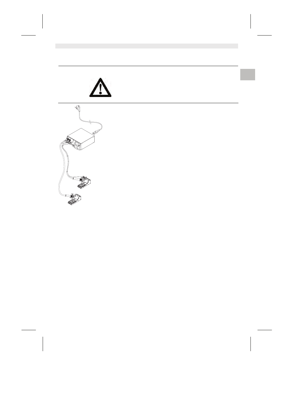
1. Carefully unpack the device.
2. Connect the soldering tools as follows:
- Connect hot air pencil (HAP) with air hose to "AIR" nipple (15),
insert with plug into socket ┌ 1 ┐ or ┌ 2 ┐ (16) on the repair
station and lock by briefly twisting clockwise.
- Connect desoldering tool with vacuum hose to "VAC" nipple
(14), insert with plug into socket ┌ 1 ┐ or ┌ 2 ┐ (16) on the repair
station and lock by briefly twisting clockwise.
- Insert the soldering tool with plug into socket ┌ 1 ┐or ┌ 2 ┐ (16)
on repair station and lock by briefly twisting clockwise.
3. Place the soldering tools in the safety holder.
4. Check whether the mains supply voltage matches that indicated
on the rating plate and whether mains power switch (13) is off.
5. Connect the control unit to the mains supply (26).
6. Switch on the device at the mains power switch (13).
After the device has been switched on, the microprocessor carries
out a self-test in which all the segments are briefly in operation. Then
the electronics switches automatically to the basic temperature
setting of 380 °C for all channels and 50 % for the "AIR" setting. If
channels are activated, the green LED (2) lights up:
−
LED lit green constantly indicates that the connected tool is being
heated up.
−
LED flashing green indicates that the preselected tool temperature
has been reached.
Active channels are indicated in the display with a triangle (22) and a
lightning symbol (21).
Note The maximum output power is limited to 251 watts.