Assembly – Viking Pump TSM151.1: H-LL 123/4123 User Manual
Page 8
SECTION TSM 151.1
ISSUE C
PAGE 8 OF 13
ASSEMBLY
Standard Mechanical Seal
(Synthetic Rubber Bellows Type)
The seal used in this pump is simple to install and good
performance will result if care is taken during installation.
The principle of the mechanical seal is contact between the
rotary and stationary members. These parts are lapped to a
high finish and their sealing effectiveness depends on
complete contact.
Viking furnishes a number of heavy-duty pumps with special
mechanical seals installed in the packing end of the pump.
These special seals are not discussed in TSM 151.1.
Information is available by contacting the factory. When
requesting special seal information, be sure to give pump
model number and serial number.
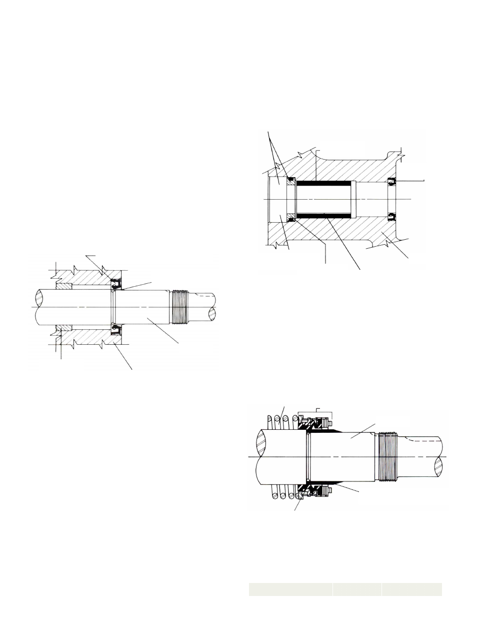
1. Install bracket bushing. If bracket bushing has a
lubrication groove, install bushing with groove at 6:00
o’clock position in bracket. If carbon graphite, Refer to
Installation of Carbon Graphite Bushings, page 11.
2. Install lip seal in bracket. Refer to Figure 7.
4. Clean rotor hub and bracket seal housing bore. Make
sure both are free from dirt and grit. Coat outer
diameter of seal seat and inner diameter of seal housing
bore with non-detergent SAE 30-weight oil.
5. Start seal seat in seal housing bore, Refer to Figure 8.
If force is necessary, protect seal face with a clean
cardboard disc and gently tap in place with a piece of
wood.
6. Place tapered installation sleeve on shaft, Refer to
Figure 9. Sleeve is furnished with H, HL, K, KK, LQ
and LL size replacement mechanical seals. Coat rotor
shaft, tapered installation sleeve and inner diameter of
mechanical seal rotary member with a generous amount
of non-detergent SAE 30 weight oil. Petrolatum may be
used but grease is not recommended.
Prior to installing rotating portion of mechanical seal, prepare
and organize rotor shaft, head and idler assemblies and
appropriate gaskets for quick assembly.
Once rotating portion of mechanical seal is installed on rotor
shaft, it is necessary to assemble parts as quickly as
possible to insure that seal does not stick to shaft in wrong
axial position. The seal should be expected to stick to the
shaft after several minutes setting time.
Never touch sealing faces with anything except clean hands
or clean cloth. Minute particles can scratch the seal faces
and cause leakage.
3. Coat idler pin with non-detergent SAE 30 weight oil and
place idler and bushing on idler pin in head. If replacing
a carbon graphite bushing, Refer to installation of
Carbon Graphite Bushings, page 11.
COAT ROTOR SHAFT, TAPERED INSTALLATION SLEEVE AND
INNER DIAMETER OF MECHANICAL SEAL WITH NON-
DETERGENT SAE 30 WEIGHT OIL BEFORE ASSEMBLY.
FIGURE 8
FIGURE 7
FIGURE 9
LIP SEAL FOR SEAL CHAMBER
TAPERED INSTALLATION
SLEEVE
SHAFT
BRACKET
BUSHING
BRACKET
LIP SEAL FOR
SEAL CHAMBER
BRACKET
BRACKET BUSHING
LUBRICATION GROOVE IN
6:00 O’CLOCK POSITION
COAT SEAL SEAT AND SEAL HOUSING BORE WITH NON-
DETERGENT SAE 30 WEIGHT OIL BEFORE ASSEMBLY.
BRACKET
BUSHING
SEAL HOUSING
BORE
SEAL SEAT
SPRING
MECHANICAL SEAL ROTARY MEMBER
SHAFT
TAPERED INSTALLATION
SLEEVE