Installation, Mounting, Alignment – Viking Pump TSM1470: HI-LO Double Pumps User Manual
Page 3: Danger, Piping/hose
SECTION TSM
1470
ISSUE
F
PAGE 3 OF 8
Mounting
1. Surfaces to which the pump mounts against must be
clean and flat.
2. Use SAE Grade 5 or better capscrews to mount the
pump.
3. The 4 mounting capscrews for GP-04 and GP-05 pumps
must have a minimum of ½ inch engagement and must
be torqued evenly to 12-15 ft.-lbs.
4. The 2 mounting capscrews for the SG-07 pumps must
have a minimum of ½ inch thread engagement and must
be torqued evenly to 50-55 ft.-lbs.
5. Do not strike or press the pump drive coupling half to
install on the pump shaft. Damage to the pump or
coupling may result. If the coupling does not slide onto
the pump shaft, inspect the coupling bore, shaft and key
for nicks or burrs and remove if present.
6. Once the pump has been mounted, place a small amount
of compatible liquid into the suction port and turn by hand
to ensure the pump turns freely.
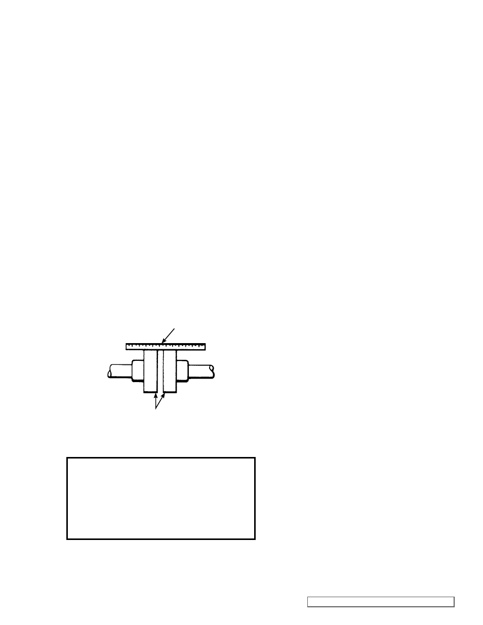
Alignment
Check alignment after mounting.
If the unit has a flexible coupling, remove any coupling guards
or covers and check alignment of coupling halves. A straight
edge (a piece of key stock will work) across the coupling
must rest evenly on both rims at the top, bottom and sides.
See Figure 3.
Danger !
before starting pump, be sure all drive equipment
guards are in place.
Failure to properly mount guards may result in seri-
ous injury or death.
Piping/Hose
The cause of many pumping problems can be traced to the
suction piping. It should always be as large in diameter and
as short in length as possible.
Before starting the layout and installation of your piping
system, consider the following points:
1. Never use piping smaller than the pump port
connections. Piping larger in diameter than the port
connection is sometimes required to reduce friction
losses.
2. Be sure the inside of the pipe is clean before installing.
3. Do not use galvanized piping.
4. When approaching an obstacle in the suction line,
go around instead of over it. Going over an obstacle
may create an air pocket. Where practical, slope the
piping so no air or liquid pockets will be formed. Air
pockets in the suction line make it hard for the pump
to prime.
5. Viking recommends using a strainer on the suction
side of the pump. The strainer will keep foreign
objects from going into the pump. A 100 mesh
strainer is recommended. Provisions must be
made for cleaning the strainer. Use of a strainer is
particularly important at start up to help clean the
system of weld beads, pipe scale and other foreign
objects.
6. On a hydraulic system, it is recommended that a
return line filter be installed having a maximum 10
micron rating.
7. A pressure relief valve is required in the discharge
line. See
Pressure Relief Valves, General page 1
item 7.
8. The pump must not be used to support piping.
Weight of the pipe must be carried by hangers,
supports, stands, etc.
9. When fastening to the pump do not impose any
strain on the pump casing. “Springing” or “drawing”
piping up to the pump will cause distortion, possible
misalignment and probable rapid wear of the pump.
Do not use the pump to correct errors in the piping
layout or assembly.
10. All joints of piping system must be tight; liquid thread
sealant will help assure leak free threaded joints.
Loose joints result in liquid leaks or suction side
leaks. Air leaks make the pump noisy and reduce
flow.
CAUTION: Be careful not to over tighten
fittings as this can cause cracked joints. Do not use
PTFE / plumber’s tape. Reduced friction makes
over tightening very easy and will result in cracked
ports.
11. Drive alignment must be checked after the piping is
hooked up.
INSTALLATION
USE STRAIGHT EDGE.
THESE SURFACES
MUST BE PARALLEL.
CHECK WIDTH BETWEEN THESE SURFACES WITH INSIDE CALLIPERS OR FEELER
GAUGE TO BE CERTAIN THE FACES ARE EQUAL DISTANCE APART AND PARALLEL.
FIGURE 3