Front panel controls and indicators – VICI 230 Dynacalibrator User Manual
Page 40
36
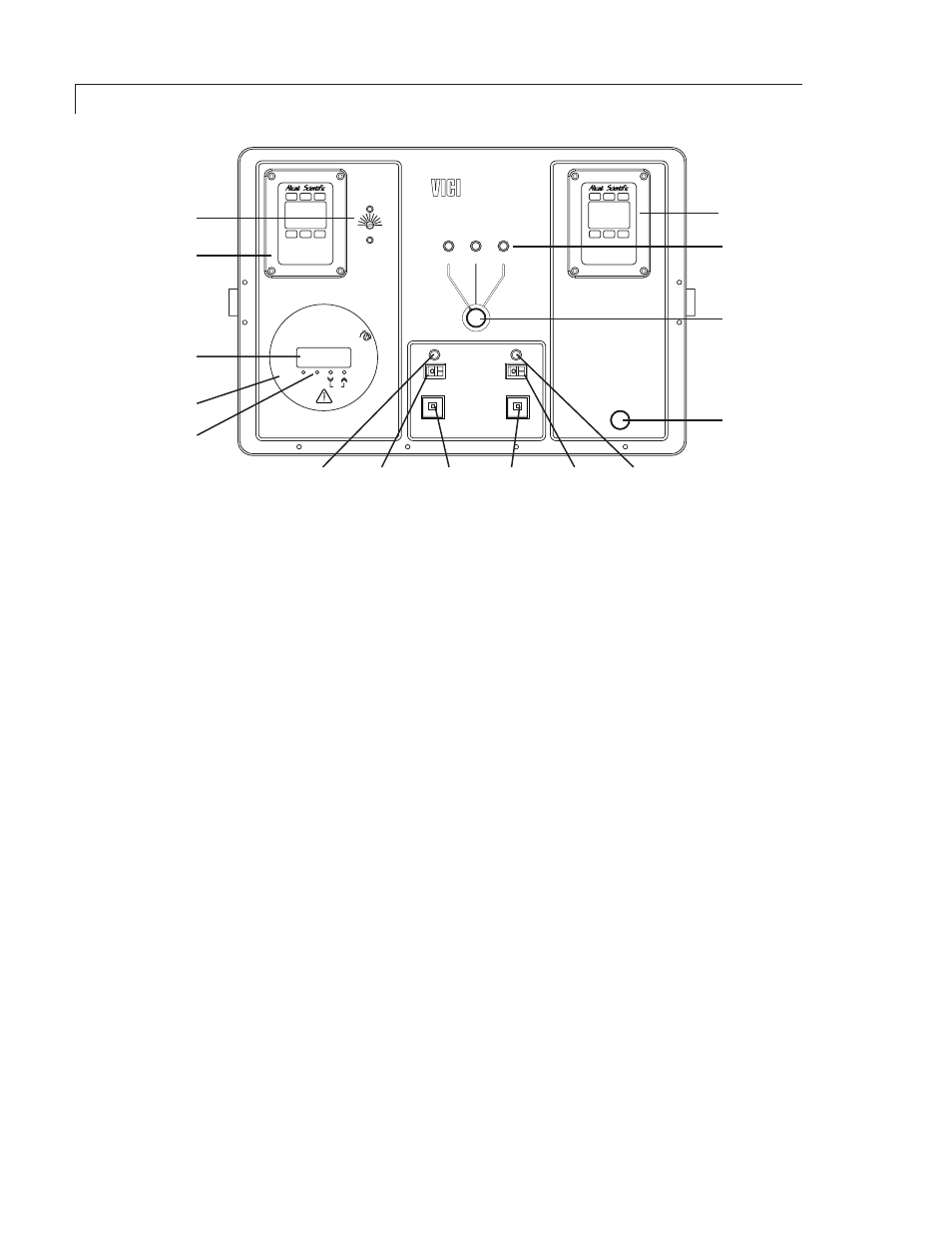
MAIN POWER switch, indicator, and circuit breaker
The rocker switch provides primary power to all circuits. The LED indicator lights when main power is on.
A 6 amp circuit breaker is installed in the main primary power input line to all circuits.
HEATER POWER switch, indicator, and circuit breaker
The rocker switch provides primary power to the heater circuits when the main power switch is on.
The LED indicator lights when heater power is on. A 4 amp circuit breaker is installed in the primary
power line to the permeation chamber heater circuits.
PERMEATION CHAMBER
This is the chamber which holds the permeation devices. A tool is provided to rotate the panel lock screw
90° counterclockwise to unlock the cap.
PERMEATION CHAMBER FLOW INDICATOR PANEL
Permeation chamber flow rates are read directly from this display. Carrier flow rates are factory set at 100
SCCM (typically), and should not be altered by the end user. Please contact VICI if a different carrier flow
rate is required.
TEMPERATURE READOUT AND CONTROLLER
The front panel displays the current chamber temperature and the control status of the instrument,
indicated by the PNL and TMP lights. The chamber temperature can be set manually through the controls
on the front panel or remotely through RS-232 communication. (Refer to the chapter entitled “Serial Port
Communications on page 16). After a temperature set point is entered by either method, it is written to
memory so that after a power failure the unit will return to the condition previously established.
DILUTION FLOW CONTROL VALVE
Turn the knob to adjust the flow rate of the dilution stream prior to mixing with carrier and trace gas.
DILUTION FLOW INDICATOR PANEL
This indicator will show the dilution flow rate in SLPM as well as providing temperature and inlet pressure
indications.
OVEN TEMPERATURE UPPER LIMIT
A thermostat provides a safety shutoff at this user-defined setpoint, usually 5 - 10 degrees above the normal
run temperature of the permeation device in use. If the oven runs out of control and the temperature goes
above this setting, power to the oven heater is shut down and a “PFAIL” indication appears in the temperature
display window.
DILUTION FLOW
INDICATOR PANEL
DILUTION
FLOW CONTROL
VALVE
MODE
SELECTOR
MODE
INDICATORS
HEATER
CIRCUIT
BREAKER
MAIN
CIRCUIT
BREAKER
HEATER
POWER
SWITCH
HEATER
INDICATOR
MAIN
POWER
INDICATOR
MAIN
POWER
SWITCH
PERMEATION
CHAMBER
CHAMBER FLOW
INDICATOR PANEL
TEMPERATURE
EQUILIBRIUM
INDICATOR
TEMPERATURE
DISPLAY
OVEN TEMPERATURE
UPPER LIMIT
Metronics Inc.
SHUTDOWN
30°
120°
MODE CONTROL
REMOTE
SPAN
ZERO
DYNACALIBRATOR
MODEL 230
PERMEATION CHAMBER
LOCK
TEMPERATURE °C
PNL TMP
SET
4A
6A
MAIN
HEATER
DILUTION
FLOW
CONTROL
MODE
Volume
Mass
Main
14.69
20.5
0.00
0.000
0.000
Air
PSIA
C
Set Pt.
1.234
SCCM
MODE
Volume
Mass
Main
14.69
20.5
0.00
0.000
0.000
Air
PSIA
C
Set Pt.
1.234
SCCM
Figure 12: Front panel controls and indicators, Electronic Flow Control option
Appendix: Electronic Flow Control Option
Front Panel Controls and Indicators