VICI 230 Dynacalibrator User Manual
Page 15
11
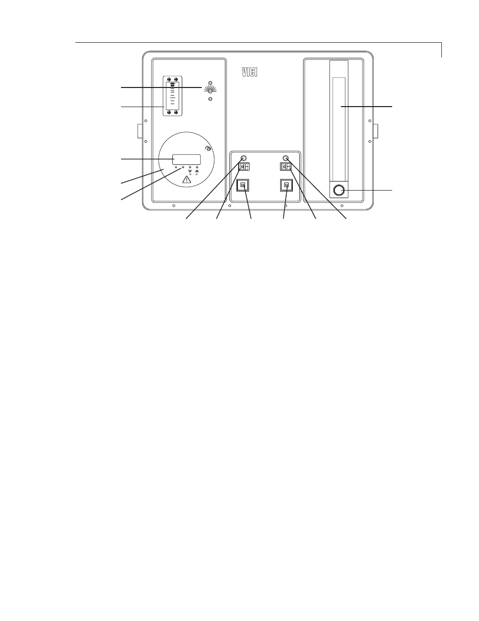
MAIN POWER switch, indicator, and circuit breaker
The rocker switch provides primary power to all circuits. The LED indicator lights when main power is on.
A 6 amp circuit breaker is installed in the main primary power input line to all circuits.
HEATER POWER switch, indicator, and circuit breaker
The rocker switch provides primary power to the heater circuits when the main power switch is on.
The LED indicator lights when heater power is on. A 4 amp circuit breaker is installed in the primary
power line to the permeation chamber heater circuits.
PERMEATION CHAMBER
This is the chamber which holds the permeation devices. A tool is provided to rotate the panel lock screw
90° counterclockwise to unlock the cap.
PERMEATION CHAMBER FLOWMETER
A ball float and gauge in the carrier stream immediately pre ceding the chamber indicates relative carrier
flow. The actual carrier flow is set at the factory. Refer to the calibration sheet at the back of the manual.
TEMPERATURE READOUT AND CONTROLLER
The front panel displays the current chamber temperature and the control status of the instrument,
indicated by the PNL and TMP lights. The chamber temperature can be set manually through the controls
on the front panel or remotely through RS-232 communication. (Refer to the chapter entitled “Serial Port
Communications on page 16). After a temperature set point is entered by either method, it is written to
memory so that after a power failure the unit will return to the condition previously established.
DILUTION FLOW CONTROL VALVE
Turn the knob to adjust the flow rate of the dilution stream prior to mixing with carrier and trace gas.
DILUTION FLOWMETER
The ball float and gauge indicate the relative dilution stream flow rate into the mixing tee, as set by the
dilution flow control knob. Factory calibrated flow rates at integral float settings are provided at the rear of
the manual.
OVEN TEMPERATURE UPPER LIMIT
A thermostat provides a safety shutoff at this user-defined setpoint, usually 5 - 10 degrees above the normal
run temperature of the permeation device in use. If the oven runs out of control and the temperature goes
above this setting, power to the oven heater is shut down and a “PFAIL” indication appears in the temperature
display window.
Getting Started
DILUTION
FLOW CONTROL
VALVE
HEATER
CIRCUIT
BREAKER
MAIN
CIRCUIT
BREAKER
HEATER
POWER
SWITCH
HEATER
INDICATOR
MAIN
POWER
INDICATOR
MAIN
POWER
SWITCH
PERMEATION
CHAMBER
CHAMBER
FLOWMETER
TEMPERATURE
EQUILIBRIUM
INDICATOR
TEMPERATURE
DISPLAY
OVEN TEMPERATURE
UPPER LIMIT
DILUTION
FLOWMETER
Metronics Inc.
SHUTDOWN
30°
120°
.15
.10
.05
CHAMBER
FLOW
DYNACALIBRATOR
MODEL 230
PERMEATION CHAMBER
LOCK
TEMPERATURE °C
PNL TMP
SET
4A
6A
MAIN
HEATER
DILUTION
FLOW
CONTROL
Figure 3: Model 230 front panel controls and indicators (Refer to page 36 for Electronic Flow Control option)