Electrical planning, Power requirements, Conduit requirements – Unitec CAME Wiring User Manual
Page 7: Wiring requirements, Loop planning and installation, General
Document
Number:
GC1004
3
Document Title:
Unitec CAME Gate and Gate Controller Installation Guide
Electrical Planning
Power Requirements
Each barrier gate requires a 115-120 VAC on a 5-Amp dedicated breaker, which should be provided
during wash construction. Most installers will have power supplied directly from one of the three phases
used to power the wash motors and controllers. If this method is used, special attention should be
given to proper grounding at the unit, as well as in the breaker panel.
Note: Follow all local and national electrical codes!
Conduit Requirements
Plan your conduit runs so that the barrier gate control signal wiring and the loop wiring enter through
the bottom of the base of the gate. Figure 1 shows a typical site layout with the following conduit runs:
• A conduit between the AC service panel and the entry units for power wiring.
• A conduit between the entry units and gates for power wiring.
• A conduit between the gate controller (located in the equipment room) and the entry units
for control signal wiring.
• A conduit between the entry units and the gates for control signal wiring.
• Conduit between the gates and loops the loop leads.
Wiring Requirements
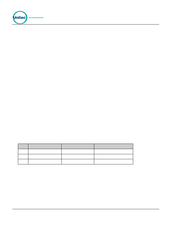
Wires to be pulled through the conduits are listed in the following tables. Wires should be 18
AWG (minimum) and color-coded to facilitate installation and troubleshooting. The quantities
shown are per lane.
Qty
From
To
Function
3
AC Service Panel
Gate
Gate Power (115 VAC)
4
Gate Controller
Entry Units
Control wires
3
Gate Controller
Gate
Control wires
Loop Planning and Installation
General
Unitec provides 18-foot vehicle detection loops that can be used for the gate arm reset or merge
loops. Two loop types are available: direct burial and saw cut installation. Direct burial loops