Unitec CAME Wiring User Manual
Page 23
Document
Number:
GC1004
19
Document Title:
Unitec CAME Gate and Gate Controller Installation Guide
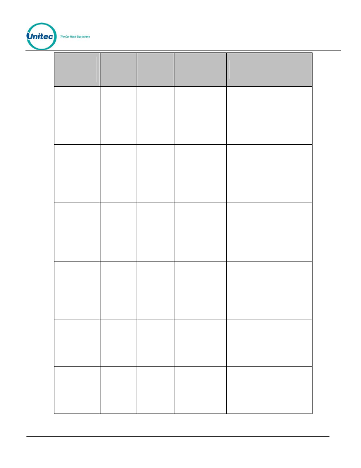
Gate
Control
Signal name
Gate
Control
Terminal
Number
Gate
Control
PLC I/O
point
Device
Connection
Descriptive Use or
Operation
Lane 1 Wash
in Use
41
Y0
Output to Wash
in use signal for
Lane 1
24VDC- is present when Gate
Controller is commanding Terminal at
Lane 1 to hold its current customer.
Signal turns off when Terminal is to
send customer through and fire wash
into queue. Note: This is a sinking
output. When testing, reference from
terminal 11(RED) to Y0. When Y0
light is on, Terminal 41(Black) to
11(Red) should measure 24VDC
Lane 2 Wash
in Use
42
Y1
Output to Wash
in use signal for
Lane 2
24VDC- is present when Gate
Controller is commanding Terminal at
Lane 2 to hold its current customer.
Signal turns off when Terminal is to
send customer through and fire wash
into queue. Note: This is a sinking
output. When testing, reference from
terminal 11(RED) to Y1. When Y1
light is on, Terminal 42(Black) to
11(Red) should measure 24VDC
Lane 3 Wash
in Use
43
Y2
Output to Wash
in use signal for
Lane 3
24VDC- is present when Gate
Controller is commanding Terminal at
Lane 3 to hold its current customer.
Signal turns off when Terminal is to
send customer through and fire wash
into queue. Note: This is a sinking
output. When testing, reference from
terminal 11(RED) to Y2. When Y2
light is on, Terminal 43(Black) to
11(Red) should measure 24VDC
Lane 4 Wash
in Use
44
Y3
Output to Wash
in use signal for
Lane 4
24VDC- is present when Gate
Controller is commanding Terminal at
Lane 4 to hold its current customer.
Signal turns off when Terminal is to
send customer through and fire wash
into queue. Note: This is a sinking
output. When testing, reference from
terminal 11(RED) to Y3. When Y3
light is on, Terminal 44(Black) to
11(Red) should measure 24VDC
Open Gate 1
51
Y4
Output to Vend
Input of Gate at
Lane 1
Tied to the Vend input of the Gate,
This line will become 24VDC- when
Gate 1 is triggered to open. Note:
This is a sinking output. When
testing, reference from terminal
11(RED) to Y4. When Y4 light is on,
Terminal 51(Black) to 11(Red) should
measure 24VDC
Open Gate 2
52
Y5
Output to Vend
Input of Gate at
Lane 2
Tied to the Vend input of the Gate,
This line will become 24VDC when
Gate 2 is triggered to open. Note:
This is a sinking output. When
testing, reference from terminal
11(RED) to Y5. When Y5 light is on,
Terminal 52(Black) to 11(Red) should
measure 24VDC