Gate to gate controller wiring, Control signal wiring, Figure 6. came gate to gate controller connections – Unitec CAME Wiring User Manual
Page 12
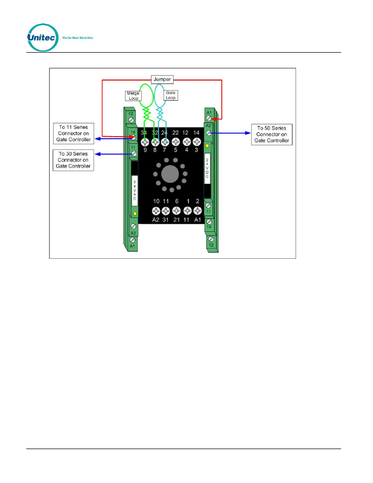
Gate to Gate Controller Wiring
Figure 6. Came Gate to Gate Controller Connections
There are 3 control wires that run from the gate to the gate controller. The gate reset loop and merge
loop wiring (if applicable) is also illustrated, above. You must remove the loop detector block to access
the block base for connecting the loop wires. The connections for each gate to the gate controller are
illustrated on the left sides of Figures 7 and 8.
Control Signal Wiring
There will be (4) control wires connected to each entry unit and (3) wires for each gate. For Portal and
Sentinel entry units, the control wires will terminate at connectors J3 and J18 on the Wash I/O board.
For the Wash Select II, the wires connect to J18 and J19 of the CPU board. The connections from the
gate controller to the gate are illustrated on the right side of Figures 7 and 8.
Figures 7 and 8 show controller wiring for up to four entry units and four gates. For installations with
fewer lanes, simply refer to the parts of the diagrams labeled for the numbers of units and gates you
are installing on site.
Document
Number:
GC1004
8
Document Title:
Unitec CAME Gate and Gate Controller Installation Guide