Vertical sidewall installations – Vermont Casting BHDR36 User Manual
Page 11
- 11 -
FINISHED
WALL
VENT
TERMINATION
(7DVRVT)
Fig. 16
STEP 5
Guide the vent termination 4" collar into the 4" pipe then the
7" collar into the 7" pipe. Do not force the venting into
position. If the pipes do not line up with the termination
collars, disassemble elbows or pipes and reattach to the
fireplace collar. (Fig. 16)
STEP 6
Recheck the fireplace to make sure that it is levelled,
properly positioned, and nailed or screwed to the floor.
If applied, the fireplace adjustable frame drywall strips
(nailing flanges) should be fastened. See Framing and
Finishing.
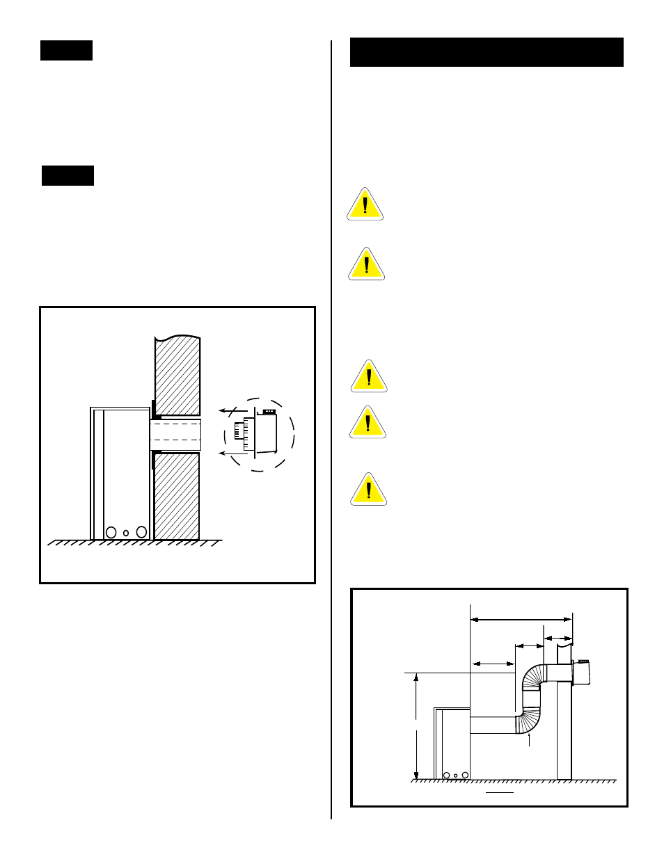
The maximum horizontal vent run is 20 feet (6100mm)
when the vertical vent rise is 7.5 feet (2286mm). Fig. 17
Fig. 17
VERTICAL SIDEWALL INSTALLATIONS
Since it is very important that the venting system
maintain its balance between the combustion air intake
and the flue gas exhaust, certain limitations as to vent
configurations apply and must be strictly adhered to.
The graph showing the relationship between vertical and
horizontal side wall venting will help to determine the
various vent lengths allowable. Fig. 21.
Minimum clearance between vent pipes and
combustible materials is one (2") inch (25
mm) on top, bottom and sides unless
otherwise noted.
When vent termination exits through
foundation less than 20" below siding outcrop,
the vent pipe must flush up with the siding. A
7DVSS must also be used.
It is always best to locate the fireplace in such a way that
minimizes the number of offsets and horizontal vent
length.
The horizontal vent run refers to the total
length of vent pipe from the flue collar of the
fireplace to the face of the outer wall.
Horizontal plane means no vertical rise
exists on this portion of the vent assembly.
For some installations, it may be desirable to
have some amount of the horizontal vent run
immediately after the fireplace. A vertical
rise must be used but can be located any-
where in the vent system, to meet the perim-
eters identified in the venting graph.
SIDE VIEW
MAXIMUM
20 ft. (6100mm)
96"' (2438mm)
VERTICAL
DIMENSION
8 ft. MINIMUM
WHEN HORIZONTAL
RUN IS 20 ft.
7DVRT90
ELBOW
,
,
,
15 ft.
(4572mm)
48"
(1220mm)
12"
(305mm)