Trail Master Suspension TM102N GM 1500 4WD/2WD SUSPENSION 4 LIFT KIT User Manual
Page 8
8
TM102N
Revised
2.4.14
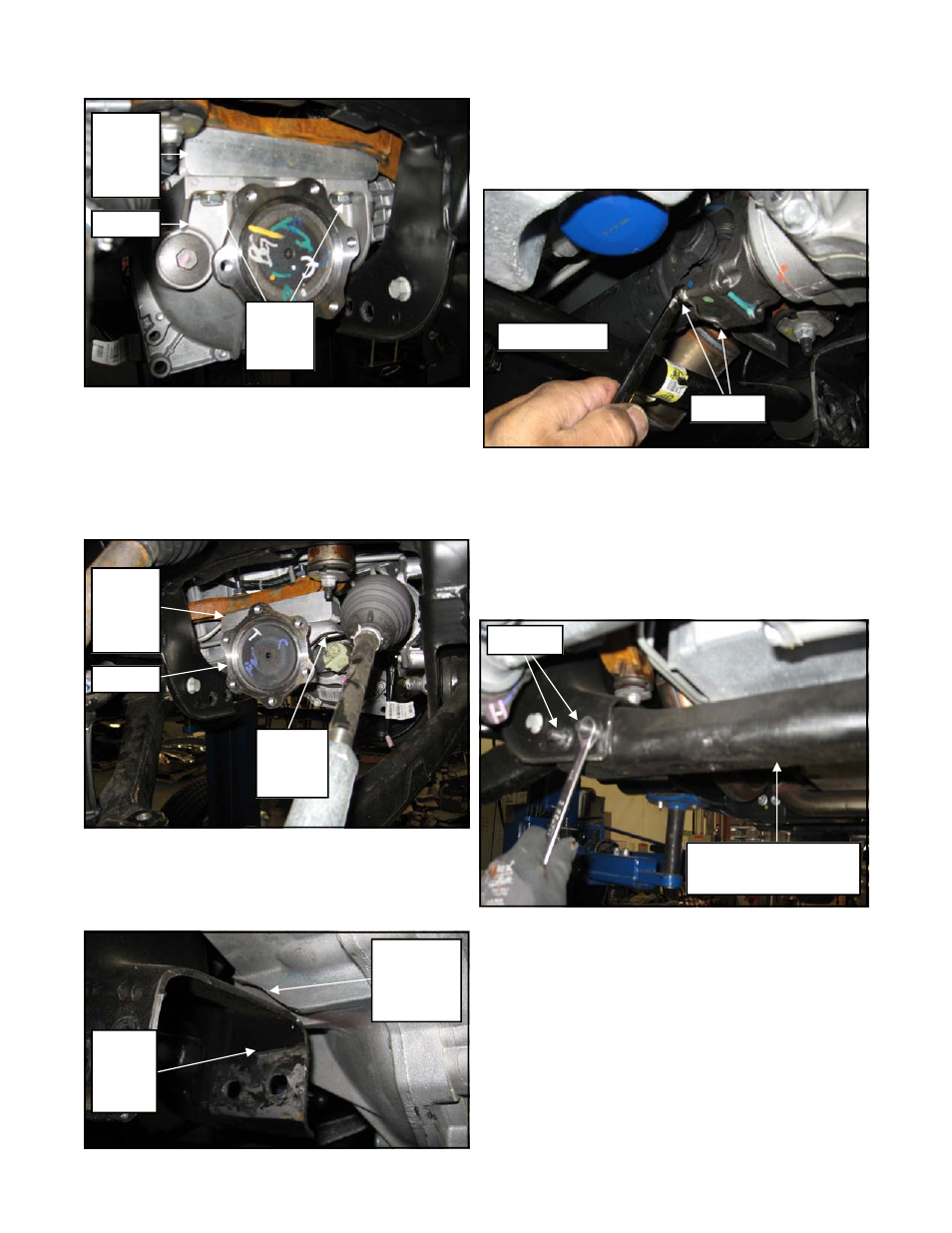
4. Secure the differential to the previously in-
stalled passenger side drop bracket (90-4519)
using the (2) supplied 12mm X 35mm, (2)
12mm lock washers and (2) 12mm fender
washers and hardware. Be sure to use thread
locker on these bolts. Torque to
55
ft./lbs.
5. Check clearance between the trimmed area of
the differential fin and the lower control arm
mounting pocket. If needed, remove more
material until adequate clearance is achieved.
6. Reinstall the front driveshaft to the front dif-
ferential using the previously removed OE
hardware. Be sure to use thread locker on
these bolts. Torque the OE bolts to
35
ft./lbs.
7. Reattach the 4WD control module wiring har-
ness clip and vent tube to the differential.
8. Re-install
the
OE rear crossmember support
brace into the frame mounting pockets using
the previously removed OE hardware. Be
sure to use thread locker on these bolts.
Torque to
55
ft./lbs.
9. Install the supplied Zerk fitting into the new
upper control arm (82-8274 drvr and 82-8277
pass). Be very careful not to cross-thread or
over tighten the fitting.
10. Install the new upper control arm (82-8274
drvr and 82-8277 pass) into the OE mounting
pockets using the previously removed OE
cam bolts. Rotate the cams so they are all the
90-4518
Drvr
Diff
Drop
OE Diff
12mm X
35mm
Bolt
90-4519
Pass
Diff
Drop
OE Diff
(2)12mm
X 35mm
Bolt
OE Rear Crossmember
Support Brace
OE Bolts
OE Driveshaft
OE Bolts
Check
Differential
Fin
Clearance
Lower
Control
Arm
Pocket