Trail Master Suspension TM102N GM 1500 4WD/2WD SUSPENSION 4 LIFT KIT User Manual
Page 6
6
TM102N
Revised
2.4.14
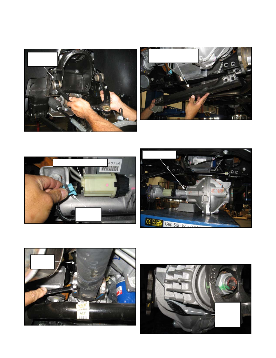
18. Unbolt the upper control arm cam bolts and
remove the upper control arm from the vehi-
cle. Save the cam bolts for reinstallation.
19. Unplug the 4WD control module wiring har-
ness clip and vent tube secure up out of the
work area.
20. Unbolt the front driveshaft from the differen-
tial and secure it out of the way of the work
area. Save the hardware for reuse.
21. Remove the OE rear crossmember support
brace from the vehicle. Save the OE hard-
ware for reinstallation.
22. Support the differential with a jack and unbolt
the driver and passenger side mounts (2 per
side). Carefully remove the differential from
the vehicle.
23. Referring to the following picture, scribe a
mark on the driver side fin portion of the front
differential. This fin area will need to be
trimmed to provide adequate clearance once
the differential is reinstalled.
OE Upper
Control Arm
OE Wiring
Clip
OE 4WD Control Module
OE
Driveshaft
OE Differential
OE Rear Crossmember
Support Brace
Area of
Differential
to Be
Trimmed