Starlight Xpress SXVR-H18 User Manual
Page 18
Handbook for the SXVR-H18
Issue 1 March 2010
18
To use your flat fields, they must first have a bias frame subtracted. Although this
may appear to be unimportant with such brightly lit and short exposures, there is the
‘bias offset’ of the camera in each image and this can produce an error in the final
correction. As we are mainly interested in the bias, any very short exposure dark
frame will give a good result. The bias subtracted images should then be averaged
together before use.
After the above procedures have been executed, the flat field will be ready for use.
Load up your image for processing, subtract the dark frame and then select ‘Apply
flat field’ in the ‘Merge’ menu. The result should be an image with very little sign of
the original artefacts.
********************************************************************
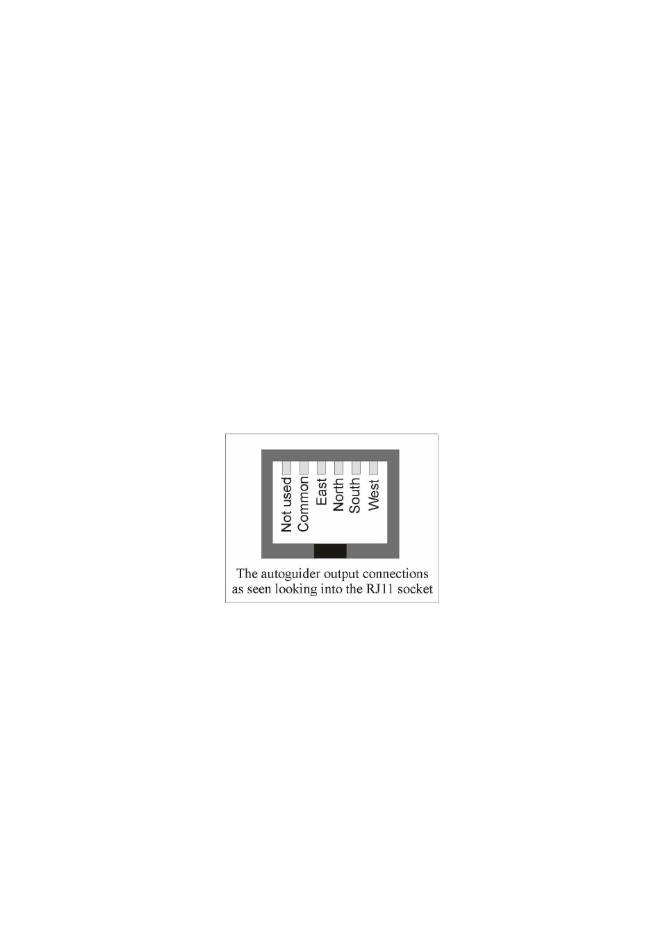
The accessory ports
The SXVR-H18 is provided with two ports for use with accessories. The Autoguider
output port is a 6 way RJ11 socket, which is compatible with the standard autoguider
input of most telescope mounts. It provides 4 active-low opto-isolator outputs and a
common return line, capable of sinking a minimum of 5mA per output. This socket
may be used for telescope control if the SXVR-H18 is employed as an autoguider, but
is primarily intended to be the control output for the optional add-on autoguider
camera head, available for use with the SXVR-H18.
The high density parallel port socket provides both control and power for the add-on
autoguider, but also includes a pair of serial ports for use with other devices.
Using the built-in serial ports
The SXVR-H18 incorporates two fast serial ports for use with external accessories.
The ports are available on 5 pins of the 18 way connector that is provided for the
autoguider and may be accessed by plugging in a ‘serial port divider box’. The divider
box and cables are available as an accessory and may be chained in series with the
autoguider cable, when the guider is in use, or may be used on its own.
The two serial connections are in the form of standard RS232 PC style plugs and
provide TX, RX and Ground connections at RS232 levels. Access is via commands
sent through the USB connection and, at the time of writing, is limited to any serial