400 series amplifier box, Siren audio wiring, Psrn4anr1 psrn4anr2 – SoundOff Signal 400 Series Handheld Siren User Manual
Page 4
1.800.338.7337 / www.soundoffsignal.com
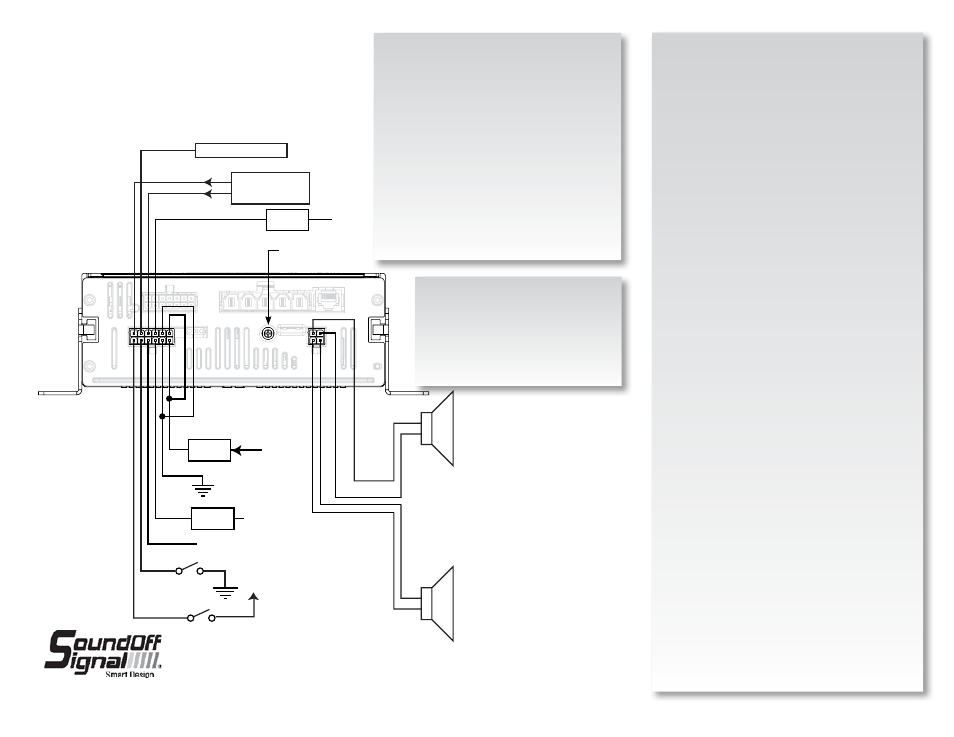
RADIO
REBROADCAST
NEUTRAL SAFETY SWITCH
IGNITION
3 amp
Fuse
YELLOW
BLUE
BLUE
ORANGE/BLACK
Horn Ring Out
Horn Ring In
Auxiliary
VIOLET
Backlight
GRAY
RADIO REBROADCAST
OUPUT LEVEL ADJUST
ORANGE/BLACK
ORANGE
GREEN/BLACK
GREE
N
Auxiliary Input: (Violet Wire)
The input is an optional input which will remotely activate the
siren when the auxiliary input wire is connected to ground. If
this feature is needed, connect the auxiliary input wire to a
switch which provides a ground connection when activated.
Park Kill disables this option.
Radio Rebroadcast Input: (Blue Wires)
The 2 – 18ga blue wires on the 12 pin Molex connector are used
to connect your two-way radio’s external speaker through the
siren amplifier and broadcast through the warning siren speaker
and is optional. Radio Rebroadcast will not work with remotely
amplified speakers due to the signal amplitude being too low.
Locate the 2 wires that connect the external speaker to the
two-way radio. T-tap one blue wire into one of the external
speaker wires. T-tap the other blue wire into the other external
speaker wire. If the blue wires need to be extended, use a
minimum of 20ga. Wire. The Radio Rebroadcast volume must
be adjusted prior to placing vehicle into service. Set the volume
of the two-way radio to the normal operating level. Press the
Radio Rebroadcast push-button on the siren control panel. With
a small screwdriver, adjust the radio rebroadcast volume poten-
tiometer located on the back of the siren amplifier to obtain the
proper volume out the speaker. Turn potentiometer clockwise to
increase volume and counter-clockwise to decrease volume.
Horn Ring Input: (White + White/Black Wire)
The input will allow the operator to control the siren func-
tion by pressing the vehicle horn ring. Refer to programming
settings for specific configuration options. Refer to wiring
diagram for details on how to connect the horn ring input wires
to the vehicle’s horn ring wiring. If this feature is required, the
installer needs to determine if the signal wire from the horn
ring is switching the +V or ground side of the circuit. Refer to
programming instructions on how to set the horn ring polarity on
the siren. Extend the horn ring input wires from the siren ampli-
fier to the horn ring switch using a minimum of 18ga wire. The
horn ring circuit is capable of handling a maximum of 5 amps
and must be fused by the installer.
Siren Speaker Output: (Orange + Orange/Black Wires), (Green
+ Green/Black) Route the Orange and Orange/Black wires from
the 4 position connector to the siren speaker. Use a minimum of
18ga. wire to extend the wires as needed. Connect the Orange
wire to the primary Speaker High wire. Connect the Orange/
Black wire to the primary Speaker Low wire. For ETSA462 only
connect the Green wire to the secondary speaker High Wire.
Connect the Green/Black wire to the secondary speaker Low
Wire.
Backlight Input: (Gray Wire)
The input will turn on the backlighting of the control panel when-
ever +V is applied to the backlight input wire.
Route the siren amplifier backlight input wire to the vehicle’s
marker light wiring using a minimum of 22ga. Wire to extend as
needed. T-tap the backlight input wire into the vehicle’s marker
light +V wire.
Park Kill Input: (Yellow Wire)
The input will silence the siren tone when the input
wire is activated. The input is typically connected
to the transmission neutral safety switch. If this
feature is required, the installer needs to determine
if the signal wire from the neutral safety switch
is switching the +V or ground side of the circuit.
Refer to the programming instructions on how to set
the park kill polarity on the siren. Extend the park
kill input wire from the siren amplifier to the neutral
safety switch using a minimum 22ga. Wire. Park kill
Vin Low is < 5Vdc.
Ignition Input: (Orange/Black Wire)
The input is required to enable the siren system.
Locate the wire on the vehicle which provides +V
when the ignition switch is turned ON. Extend the
ignition input wire as needed using a minimum of
22ga. Wire and tap into the vehicle ignition wire.
Wire capacity requirements for siren
amplifier (incoming power)-each supply and
ground wire.
0-10 Feet: 14 AWG
10-20 Feet: 12 AWG
20-30 Feet: 10 AWG
30+ Feet: Consult Factory to determine
requirements
SIREN AUDIO WIRING
BLACK
+V
5 amp
Fuse
WHITE
WHITE/
BLACK
+V
RED
PRIMARY
ETSA461 OR
ETSA462
SECONDARY
ONLY ON
ETSA462
CN6
CN2
400 SERIES AMPLIFIER BOX
PSRN4ANR1
PSRN4ANR2
20 amp
Fuse
ORANGE
ORANGE/ BLACK
GREEN
GREEN/ BLACK
USE ONE 11 OHM
SPEAKER PER OUTPUT
4
ETSA46(x)HPP-cvr 11.13
SPKR A
SPKR B