Left panel connectors and controls – Sound Devices 702 User Manual
Page 14
702 User Guide and Technical Information
12
v. 2.67
Features and specifications are subject to change. Visit www.sounddevices.com for the latest documentation.
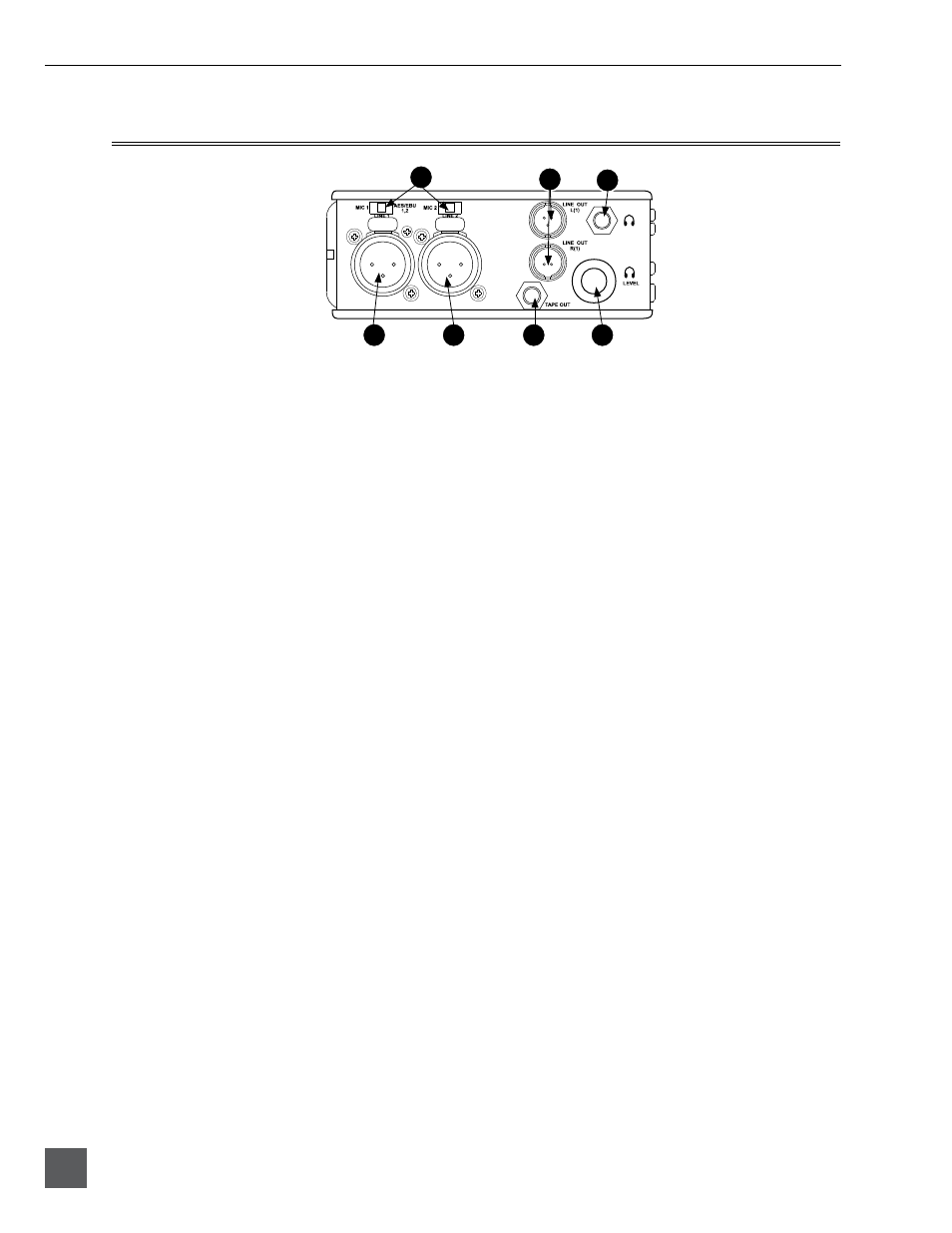
Left Panel Connectors and Controls
702
1
7
6
5
4
2
3
1)
XLR Input 1/AES3 Input 1&2
Dual function input connection. Input
type set with switch above. Active-bal-
anced analog microphone- or line-level
input for input 1. Transformer-balanced
two-channel AES3 input (1 and 2).
2)
XLR Input 2
Active-balanced analog microphone- or
line-level input for input 2.
3)
Mic-Line Input Switch
Selects the input level and mode of the
associated XLR input connector. Input 1
also can be selected for AES3 input.
4)
TA3 Master (L/R) Analog Outputs
Active-balanced, line-level analog L/R
outputs for the Master Output Bus. Pro-
gram source and attenuation level are
user selectable. Pin-1 ground, pin-2 (+),
pin-3 (
–
).
5)
Headphone Output
3.5 mm TRS stereo headphone connec-
tor. Can drive headphones from 8 to
1000 ohm impedances to very high lev-
els. Tip-left, ring-right, sleeve-ground.
6)
Headphone Level
Adjusts the headphone output level.
NOTE: the 702 is capable of producing
ear-damaging levels in headphones.
7)
Tape Output
Unbalanced tape (–10 dBv nominal)
output on 3.5 mm TRS stereo connector.
Signal source is identical to the Master
Output Bus. Tip-left, ring-right, sleeve-
ground.