Sky-Watcher AZ EQ6 User Manual
Page 17
17
4.
Intermittent one flash: The PPEC training routine has been triggered, but the
controller in the mount has not received the worm index signal and the correc-
tion-recoding has not started yet.
5.
Intermittent two flashes: The PPEC training routine has been started and the
controller in the mount has received the worm index signal and started to record
the PE correction. When the intermittent two flashes stops, it means the PPEC
training has finished.
6.
Intermittent, three flashes: Sidereal tracking with PEC is now enabled.
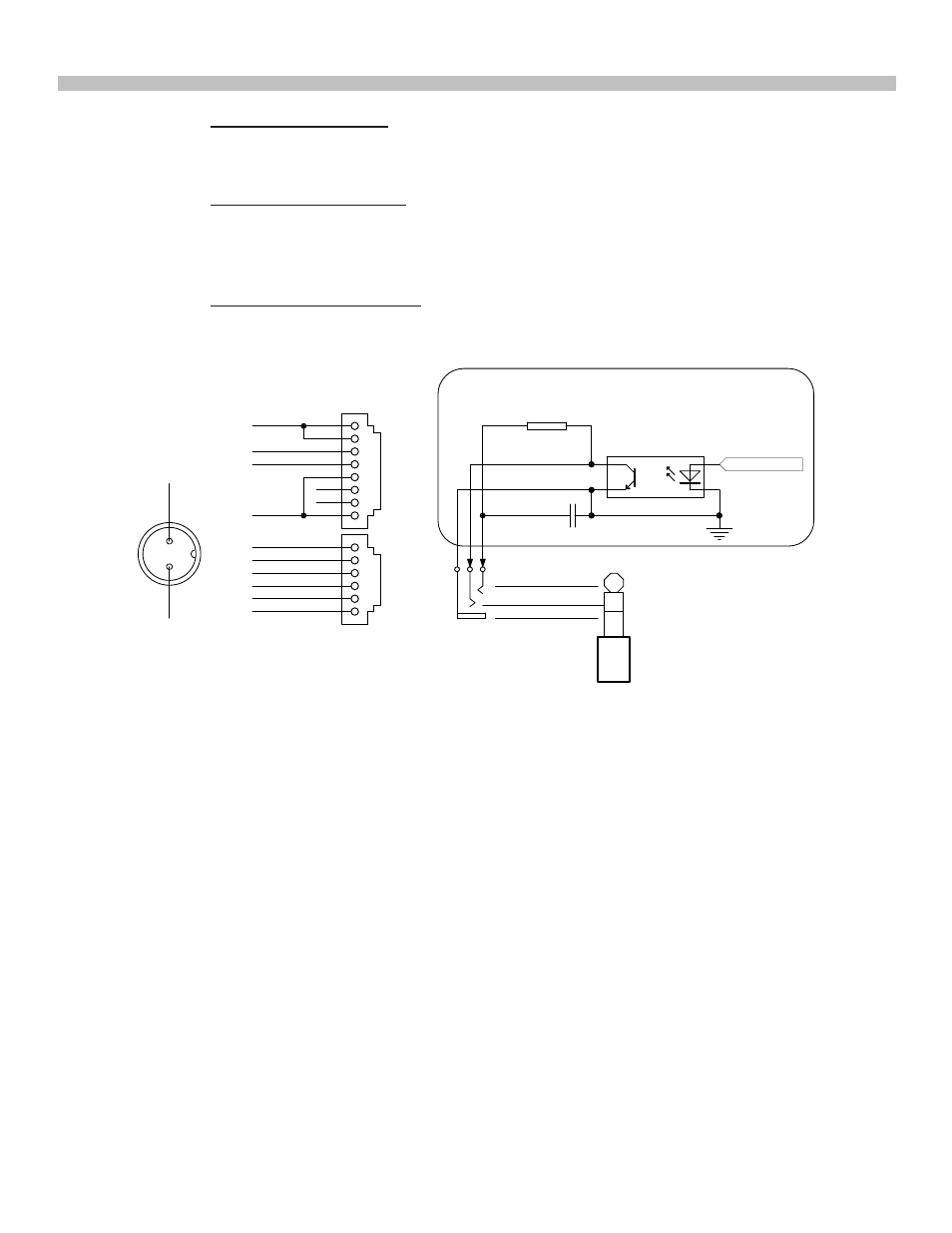
4.3 Pinout of the Interfaces:
Fig. 4.3
PART IV: ELECTRONIC CONTROL INTERFACE
Note:
• The SNAP port provides two trigger signals to the stereo plug. The signal to the head of the
plug is issued slightly later than the signal to the ring of the plug.
• For a camera which only needs a shutter-release signal, either trigger signals will work. For
a camera which requires a “Focus” signal ahead of the shutter-release signal, both signals
should be connected properly.
• The camera control cable shipped with the AZ-EQ6 GT mount is for a Canon EOS series
DSLR camera. Cable for other cameras is optional and can be ordered separately.
• Output Voltage: DC 11V (minimum) to DC 16V (maximum). Voltage not in this range might
cause permanent damage to the motor controller or the hand controller.
• Output Current: 4A for power supply with 11V output voltage, 2.5A for power supply with
16V output voltage.
• Do not use an un-regulated AC-to-DC adapter. When choosing an AC adapter, it is recom-
mended to use a switching power supply with 15V output voltage and at least 3A output
current.
• If the power voltage is too low, the motor controller will stop the motors automatically.
4.4 Power Supply Requirements
2
3
4
1
5
6
7
8
HAND CONTROL
GND
Vpp+
RX(3.3V)
TX(3.3V)
2
3
4
1
5
6
AUTO GUIDE
GND
+5V
RA+
RA-
DEC+
DEC-
R
560
C
10uF/25V
SNAP
Optoisolator
GND
GND
Vpp+
POWER
Control Signal
Internal Circuit
GND
TRIGGER
DELAYED
TRIGGER