Rite-Ride 2550 User Manual
Page 6
towards the front of the truck, on both sides. When the air spring is in
place and properly aligned, install the internal tooth lock washer and
¾"-16 hex nut onto the stud of the air spring. On the right side, align
the heat shield before tightening the ¾"-16 hex nut on the air spring.
Make sure the heat shield will not interfere with the normal operation
of the air spring or the vehicle’s suspension. Do not position the face of
the directly over the axle, as it may contact the axle on full suspension
compression. Next install the air fitting into the stud of the air spring.
Tighten the air fitting securely to engage the orange thread sealant.
STEP 4—LOWER BRACKET INSTALLATION
Four wheel drive trucks will have a cast iron jounce stop as shown
in Figures “A” and “C”. If this jounce sop is present, the height set-
ting of the lower bracket assembly needs to be just above the jounce
stop (to clear the head of the bolt in the bottom of the air spring). On
two wheel drive trucks assemble the lower assembly to the shortest
setting. See Figure “D”.
The lower bracket assembly should be installed on the lowest
setting possible for the truck. See Figure “D”.
The saddle and lower bracket are bolted together using four 3/8"-
16 x 1" bolts and flange nuts to make up the lower bracket assembly.
When the assembly is bolted together at the proper height, install the
3/8"-16 x ¾" flange blot through the forward hole on the lower bracket
into the bottom of the air spring and tighten.
Place the lower bracket assembly against the leaf spring stack
making sure that the top of the lower bracket fits in between the axle
U-bolts. Place the bail clamp around the axle block and install the
3/8"-16 flange nuts onto the bail clamp and tighten.
Insert the carriage bolts through the square holes on the lower
bracket assembly being careful not to chaff or pinch the brake lines
on the axle. Next push the axle strap onto the bottom of the axle and through the carriage bolts. When the 3/8"-16
flange nuts are tightened, they will draw the axle strap into place.
STEP 5—AIR TUBING INSTALLATION
Uncoil the air tubing and cut into two equal lengths. DO NOT FOLD OR KINK THE TUBING. Try to make the cut as
square as possible. Insert one end of the tubing into the straight fitting installed in the top of the air spring. Push the
tubing into the fitting as far as possible. Select a location on the vehicle for the air inflation valves. This can be on
the bumper or the body of the truck, as long as it is protected so the valves will not be damaged. Drill a 5/16" hole
and install the air inflation valve using two 5/16" flat washers per valve as supports. Route the air tubing from the
air spring to the inflation valve, avoiding direct heat from the engine and exhaust pipe while keeping it away from
sharp edges as well. The air tubing should not be bent or curved sharply as in may kink with time. Secure the tubing
in place with the tie-wraps provided. Push the end of the air tubing into the inflation valve as far as possible. See
Figures “E” and “F”.
STEP 6—CHECK THE SYSTEM
Visually check for loose attaching bolts. Make sure that no part of the truck is rubbing against the air springs. Again,
make sure that the truck’s brake lines are not pinched or being rubbed by any part of your air spring kit.
Inflate the air springs to 50 psi and check the fittings for air leaks with an applied solution of soap and water. If
a leak is detected, deflate the air spring by depressing the valve core. The tubing can easily be removed from the
fittings by pushing the collar towards the body of the fitting while pulling out the tube. Next check the tubing connec-
tion to ensure that the air tubing is cut as square as possible and that it is pushed completely into the fitting.
If a leak is detected where the air fitting screws into the air spring, gently tighten the air fitting into the spring
until the leak stops. Also check the core of the inflation valve. The valve core can be tightened using the valve cap
provided. Re-inflate the air springs and check for leaks again if needed. This now completes the installation. Recon-
nect the battery cable and remove the wheel chocks.
NOTE: THE OPERATION PRESSURE OF THIS KIT IS 5 PSI MIN. TO 100 PSI MAX.
Too much air pressure in the air springs will result in a firmer ride, while too little air pressure will allow the
air springs to bottom out over rough conditions. Too little air pressure will also not provide the improvement
in handling that is possible. TO PREVENT POSSIBLE DAMAGE MAINTAIN A MINIMUM OF 5 psi IN THE AIR
SPRINGS AT ALL TIMES.
Once the air springs are installed, it is recommended that the vehicle not be lifted by the frame, as over-extension
may occur, resulting in damage to the air springs. However, should it become necessary to raise the vehicle by the
frame, deflate both air springs completely.
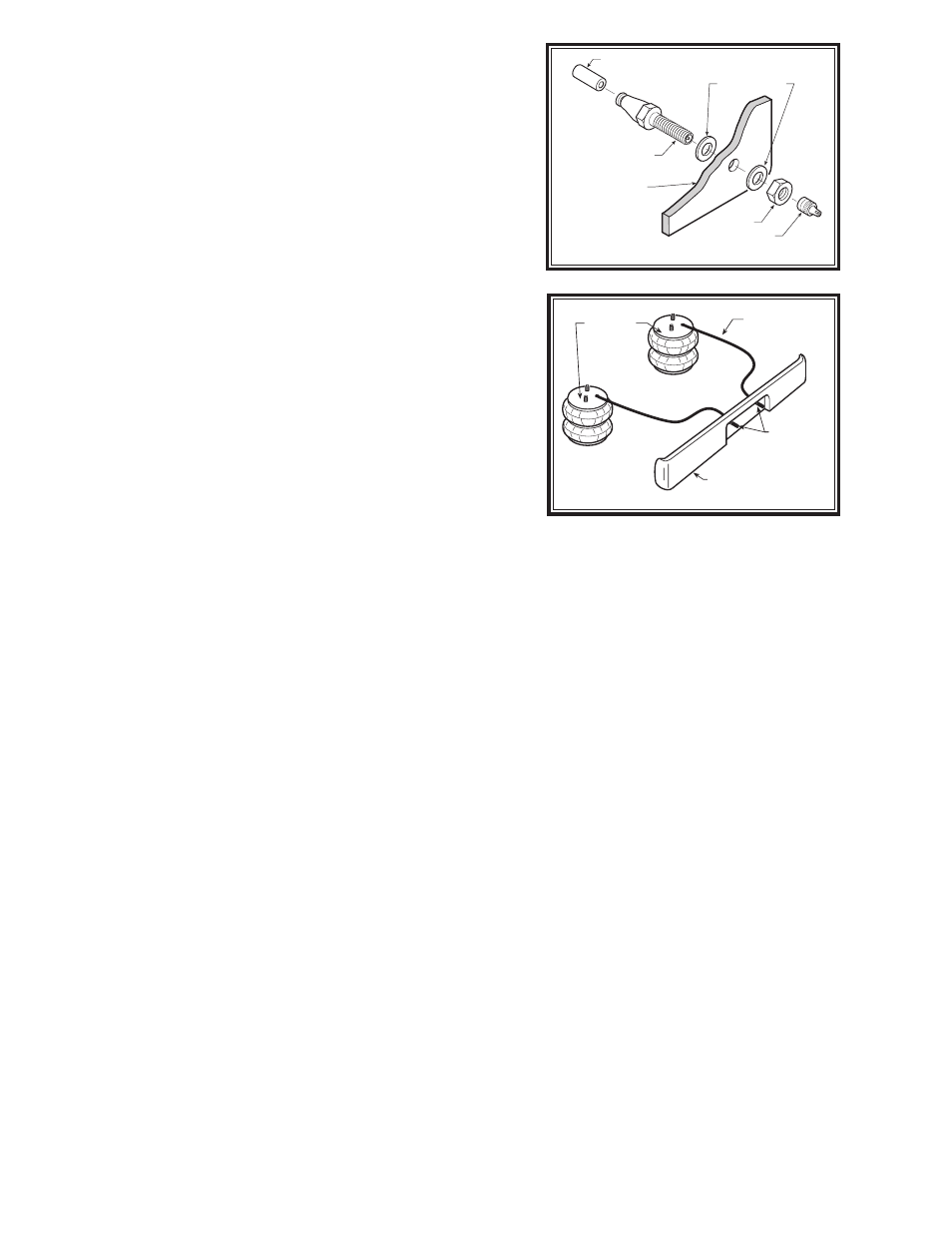
Figure “F”
AIR HOSE
INFLATION
VALVES
BUMPER
AIR
SPRINGS
AIR LINE
PUSH-TO-CONNECT
INFLATION VALVE
FLAT WASHER
HEX NUT
VALVE CAP
BODY OF
VEHICLE
Figure “E”