Rite-Ride 2528 User Manual
Page 4
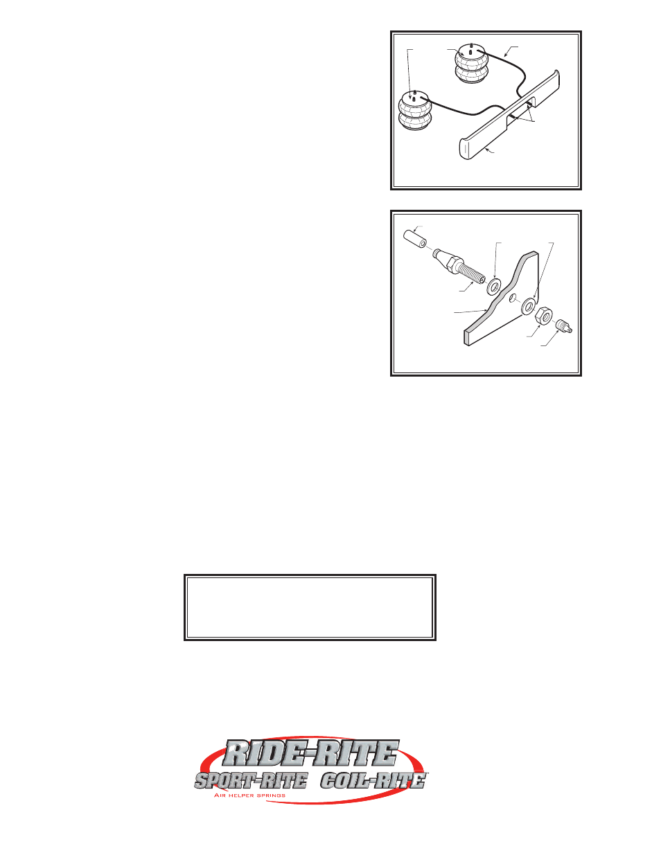
AIR LINE
PUSH-TO-CONNECT
INFLATION VALVE
FLAT WASHER
HEX NUT
VALVE CAP
BODY OF
VEHICLE
STEP 6 — CHECK THE AIR SYSTEM
Once the inflation valves are installed, inflate the air helper springs to
70 psi and check the fittings for air leaks. Using a spray bottle, apply
a solution of soap and water to the fittings. If a leak is detected at a
airline tubing connection then check to make sure that the airline is cut
as square as possible and that it is pushed completely into the fitting.
The airline tubing can easily be removed from the fittings by exhausting
all the pressure in the air springs and then pushing the collar towards
the body of the fitting and then, with a gentle pull, remove the airline
tubing. If a leak is detected where the air fitting screws into the spring,
screw the air fitting into the air spring one additional turn or until the
leak stops. Reinstall the tubing and reinflate the air springs and check
for leaks as noted above.
This now completes the installation. Install the wheels and torque
the lug nuts to the manufacturer's specification. Raise the vehicle by
the axle and remove the jack stands. Lower the vehicle to the ground.
Reattach the negative battery cable and remove the wheel chocks
from the front wheels. Before proceeding, check once again to be
sure you have proper clearance around the air springs. With a load on
your vehicle and the air helper springs inflated, you must have at least
1/2" clearance around the air springs. As a general rule, the air helper
springs will support approximately 50 lbs. of load for each psi of infla-
tion pressure (per pair). For example, 50 psi of inflation pressure will
support a load of 2500 lbs. per pair of air helper springs. FOR BEST
RIDE use only enough air pressure in the air helper springs to level the
vehicle when viewed from the side (front to rear). This amount will vary
depending on the load, location of load, condition of existing suspen-
sion and personal preference.
NOTE:
Too much air pressure in the air helper springs will result in a firmer
ride, while too little air pressure will allow the air helper spring to bot-
tom out over rough conditions, and will not provide the improvement
in handling that is possible. TO PREVENT POSSIBLE DAMAGE
MAINTAIN A MINIMUM OF 5 psi IN THE AIR HELPER SPRINGS
AT ALL TIMES.
FIGURE “E”
AIR HOSE
INFLATION
VALVES
BUMPER
AIR
SPRINGS
FIGURE “F”
www.ride-rite.com
NOTE:
MIN PRESSURE
5 PSI
MAX PRESSURE (LOADED)
100 PSI