Rite-Ride 2528 User Manual
Page 3
NOTE:
Please read thorough this manual completely
before installing the air spring kit to your
vehicle. A heat shield is required on the exhaust
side of the vehicle as noted in Step 4. If your
truck has an aftermarket dual exhaust system,
you may have to order an extra heat shield.
STEP 1— PREPARE THE VEHICLE
Remove the jounce bumper located under the
frame rail. The jounce bumpers will pull out of
the jounce bumper welded to the frame
STEP 2— PRE-ASSEMBLE THE KIT
Place the carriage bolts into the square holes of the lower bracket and
then fasten the lower bracket to the air helper spring using a 3/8"-16 x
5/8" flat head bolt. See Figure “A”.
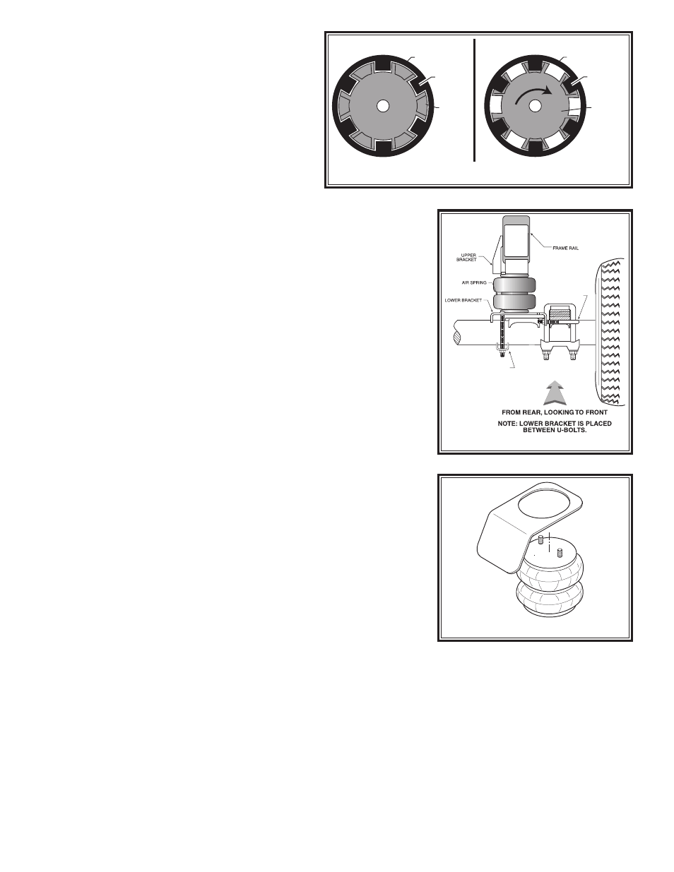
STEP 3 — INSTALLING THE ASSEMBLY TO THE VEHICLE
Place the Insert into the jounce bumper cup. Align the cut-outs of the
insert with the flanges inside the cup. Turn the insert so the recessed
portion of the insert captures the flanges. See Figure “B”. Place the
right upper bracket onto the frame and secure it to the frame using a
3/8"-16 x 2" flat head bolt threaded into the insert. Select one air helper
spring from your kit and insert the large stud into the large hole, and
the alignment pin in the small hole. Use whichever hole provides the
best alignment. Secure the air spring to the bracket using a 3/4"-16
hex nut and 3/4" internal tooth lock washer. See Figure “A”. Install the
male fitting into the air spring. Tighten the air fitting securely to engage
the orange thread sealant. Install the bail clamp under the leaf springs
from the outside of the leaf stack into the holes in the legs of the lower
bracket. Secure the bail clamp to the lower bracket with the 3/8/"-16
flange nuts and draw the lower bracket against the leaf stack. See Fig-
ure “C”. Attach the lower bracket to the axle using the bracket clamp
and the 3/8"-16 flange nuts, see Figure “A”. Once the assembly is in
place, you must have a minimum of 1/2" clearance around the air spring
for proper operation.
Note: The use of a heat shield is required on the passenger's
side of the vehicle, see Figure “D”. The heat shield will mount
between the upper bracket and the air helper spring. Bend the heat
shield so it will fall halfway between the air helper spring and the clos-
est point on the exhaust. Be sure that the heat shield will not contact
any other component as the suspension compresses (i.e. brake lines,
shock absorbers, lower bracket assembly).
STEP 4 — INSTALLATION OF THE DRIVER’S
SIDE ASSEMBLY
Follow steps 1-3 for assembly and installation of the driver’s side.
STEP 5 — INSTALL THE AIR LINE AND INFLATION VALVE
Uncoil the airline tubing and cut it into two equal lengths. DO NOT FOLD OR KINK THE AIRLINE TUBING. Try to
make the cut as square as possible. Insert one end of the airline tubing into the air fitting installed in the top of the
air helper spring. Push the airline tubing into the fitting as far as possible.
Select a location on the vehicle for the air inflation valves. The location can be on the bumper or the body of the
vehicle, as long as it is in a protected location so the valve will not be damaged, but maintain accessibility for an air
chuck, see Figure “E”. Drill a 5/16" hole and install the air inflation valve using two 5/16" flat washers per valve as
supports see Figure “F”.
Run the airline tubing from the air helper spring to the valve, routing it to avoid direct heat from the engine,
exhaust pipe, and away from sharp edges. Thermal sleeves have been provided for these conditions. The airline
tubing should not be bent or curved sharply as it may buckle. Secure the airline tubing in place with the nylon ties
provided. Push the end of the airline tubing into the inflation valve as illustrated see Figure “F”.
FIGURE “C”
BAIL CLAMP
AXLE STRAP
PASSENGER’S SIDE
JOUNCE BUMPER
CUP
FLANGE
INSERT
UNLOCKED
JOUNCE BUMPER
CUP
FLANGE
INSERT
LOCKED
RO
TATE
FIGURE “B”
FIGURE “D”
HEAT SHIELD