Rite-Ride 2320 User Manual
Page 5
S
TEP
5 – M
ARK
AND
DRILL
HOLES
IN
THE
FRAME
Visually align the air spring so that it is verti-
cally straight and the upper and lower brackets
are parallel. (Note: The upper bracket should not
extend beyond the top of the frame rail.) see
Figure “A” and “B”. Check the “X” dimension
on both sides of the air spring, these dimensions
should be the same (refer to Figure “B”). Before
drilling the holes make sure all electrical, brake
and fuel lines are cleared from the path of the drill.
In order to prevent any damage to these lines it is
recommended that a piece of wood be placed
between the frame rail and the existing lines during
drilling. With the air spring assembly in place,
mark the upper left hole with a center punch. Drill
the hole using a 3/8" drill bit.
S
TEP
6 – (A
LL
) A
TTACHING
THE
UPPER
BRACKET
NOTE: GM vehicles - The upper bracket aligns
on the frame where a box frame and C-channel
frame are welded together. No spacers are need. Mark and drill the holes and fasten the reward flange to the frame
first, then the forward flange.
Your kit includes 3/8" nut plates as well as 3/8" flange nuts that will be used to attach the upper bracket to the
frame. These nut plates allow entry into the frame in the areas where it would be difficult to use a wrench. Once the
hole has been drilled, attach the upper bracket using a 3/8" x 1 1/2" hex bolt and a nut plate (finger tight). (On Ford
vehicles use the brake line relocating bracket) This will allow you to adjust the location of the upper bracket. Once
the positioning of the upper bracket is parallel with the lower bracket and the “X” dimensions are the same, drill the
remaining holes in the frame rail using the upper bracket as a template. Use the 3/8" x 1 1/2" hex bolts and nut plate
on the front portion of the frame rail. Use the 3/8" x 1 1/2" hex bolts, large flat washers (inside of the frame) and the
flanged hex nuts to fasten the upper bracket to the frame rail. Figure “A”. Tighten the bolts to 28 – 32 ft. lbs. Once
the upper bracket is secure, align the bottom of the air spring side to side to ensure that it is vertical. Tighten
the bolt securing the lower bracket to the air spring.
S
TEP
7 - I
NSTALLATION
OF
THE
RIGHT
SIDE
ASSEMBLY
Follow steps 1-5, reversing all orientations, for assembly and installation of the passenger’s side assembly. Both air
helper springs will install just to the front of the axle.
S
TEP
8 - I
NSTALL
THE
AIR
LINE
AND
INFLATION
VALVE
Uncoil the air tubing and cut it into two equal lengths. DO NOT FOLD OR KINK THE TUBING. Try to make the
cut as square as possible. Insert one end of the tubing into the elbow fitting installed in the top of the air helper spring.
Push the tubing into the fitting as far as possible.
Select a location on the vehicle for the air inflation valves. This can be on the bumper or the body of the vehicle,
as long as it is protected so the valves will not be damaged (see Figure “D”). Drill a 5/16" hole and install the air inflation
valve using two 5/16" flat washers per valve as supports (see Figure “E”). Route the tubing from the air helper spring
to the inflation valve, avoiding direct heat from the engine, exhaust pipe, and away from sharp edges. The air line tubing
should not be bent or curved sharply as it may buckle with age. Secure the tubing in place with the nylon ties provided.
Push the end of the air line tubing into the inflation valve as illustrated (see Figure “E”).
S
TEP
9 - C
HECK
THE
AIR
SYSTEM
Once the inflation valves are installed, inflate the air helper springs to 50 psi and check the fittings for air leaks with
an applied solution of soap and water. If a leak is detected, deflate the air spring by depressing the valve core. The tubing
can easily be removed from the fittings by pushing the collar on the fitting towards the body of the fitting while pulling
out the tube. Next, check the tubing connection to ensure that the air tubing is cut as square as possible and that it is
pushed completely into the fitting.
If a leak is detected where the air fitting screws into the air spring, gently tighten the air fitting into the spring
until the leak stops. Also, check the core of the inflation valve. This valve core can be tightened using the cap. Re-
inflate the air spring and check for leaks again if needed.
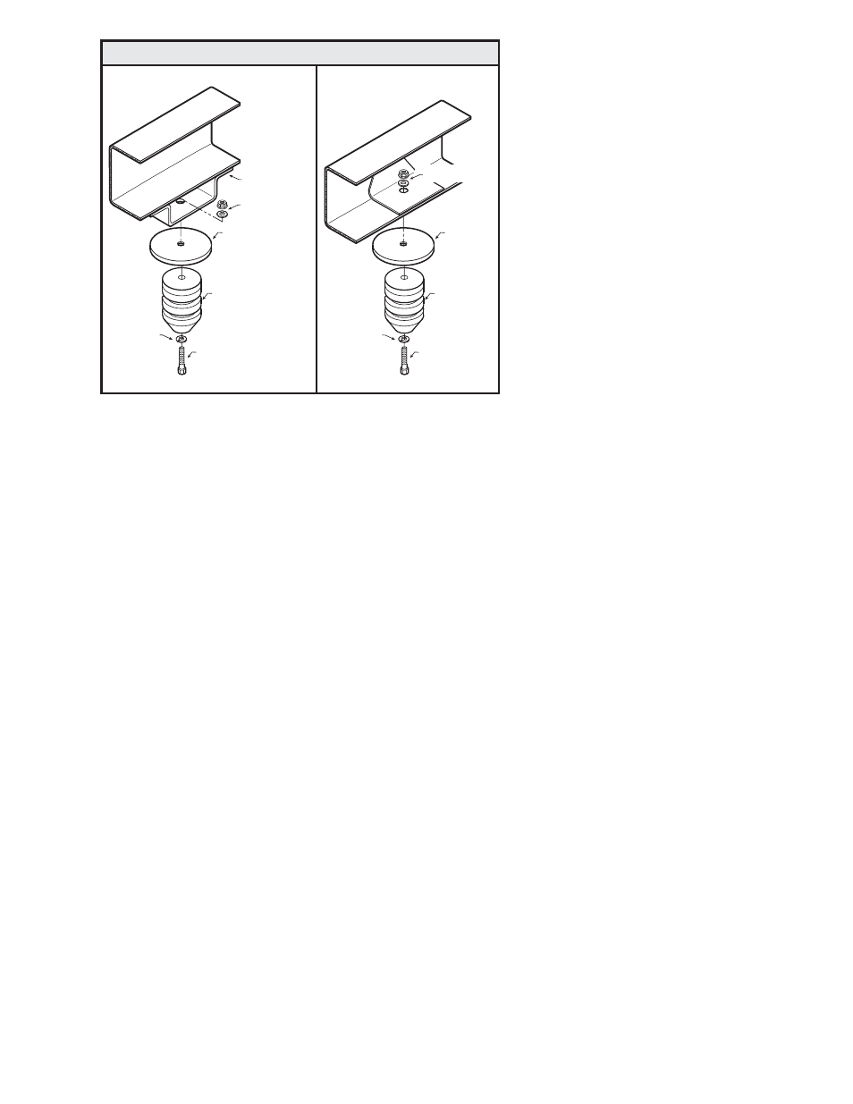
M10 X 40MM
HEX BOLT
SPACER
LOCK WASHER
FLANGE LOCK NUT
& FLAT WASHER
JOUNCE
BUMPER
FLANGE LOCK NUT
& FLAT WASHER
JOUNCE BUMPER
BRACKET
M10 X 40MM
HEX BOLT
SPACER
LOCK WASHER
JOUNCE
BUMPER
4x4 TRUCKS
2WD TRUCKS
GMC / CHEVROLET JOUNCE BUMPER SPACER
Figure "F"