1 - p, 2 - p, 3 - a – Rite-Ride 2320 User Manual
Page 4: (gm trucks)
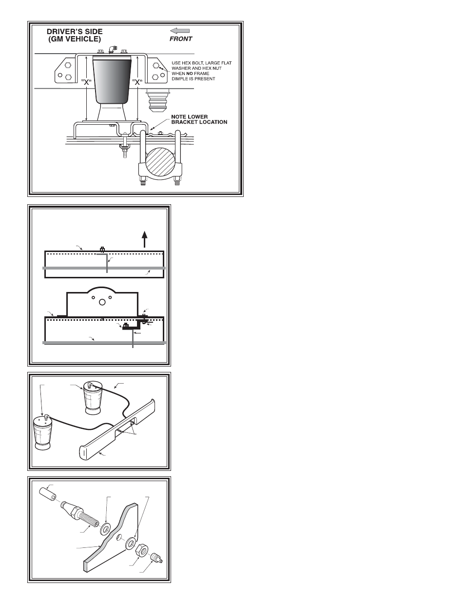
FRAME
BRAKE LINE
EXISTING
BRAKE LINE
CLIP
FRAME
BRAKE
LINE
EXISTING
BRAKE LINE
CLIP
UPPER
BRACKET
HEX
BOLT
NUT
PLATE
BRAKE LINE
RELOCATION
BRACKET
BRAKE CLIP RELOCATION
(FORD VEHICLE ONLY)
WHEEL
“X” = 7.25” - 9”
BRACKET SHOULD BE
AS HIGH AS POSSIBLE
WITHIN THIS RANGE.
AIR LINE
PUSH-TO-CONNECT
INFLATION VALVE
FLAT WASHER
HEX NUT
VALVE CAP
BODY OF
VEHICLE
Figure "B"
S
TEP
1 - P
REPARE
THE
VEHICLE
First, measure the distance between the tire
and frame. If there is less than 6" of clearance, do
not proceed. There should be no extra weight in
the bed of the truck so that the initial ride height of
your air helper spring kit will be correct. With the
vehicle on a solid, level surface chock the front
wheels. Raise the vehicle by the axle and remove
the rear wheels. After the removal of the wheels,
lower the vehicle so the axle rests on jack stands
rated for your vehicles weight. Remove the nega-
tive battery cable.
THE “X” DIMENSION.
Throughout this manual we refer to an “X”
dimension. This is the initial, un-inflated over-
all height of the air spring. Both right and left
sides should be installed at the same height.
The “X” dimension on this air spring is 7.25"to
9". The upper bracket shopuld be as high as
possible within this range.
The air spring may require some stretch-
ing to achieve this dimension.
S
TEP
2 - P
RE
-
ASSEMBLE
THE
KIT
Select one air helper spring from your kit. Install the upper bracket
by aligning the three holes on the air spring with the holes on the upper
bracket. Fasten the upper bracket to the air spring using the 3/8" x 3/4"
hex bolts as shown in Figure “A”. Install the air fitting as shown in
Figure “A”. Tighten the air fitting to make contact with the Teflon ring
and then tighten an additional 1/2 turn. No thread sealant is needed.
Insert the bail clamp into the lower bracket. Next, attach the lower
bracket and disk to the air spring using the 3/8"x 3/4" hex bolt (see
Figure “A”). Note: Finger tighten the bolt securing the lower bracket
and disk allowing the air spring to move freely. This will be tightened
after alignment in Step 6.
S
TEP
3 - A
TTACH
LOWER
BRACKET
TO
LEAF
SPRING
Place the assembly on the left side on top of the leaf spring stack
forward of the axle (see Figure “A” and “B”). Note the slight difference
in the lower bracket position on top of the leaf spring plate between Ford
and GM. Attach the lower bracket to the leaf stack using the bail clamp
(installed earlier), the bracket strap, and the flange lock nuts as shown
in Figure “A” and “B”. (Tighten to 15-20 ft. lbs.)
S
TEP
4- (GM TRUCKS)
Remove the jounce bumpers located under the frame rail by removing
the bolt located inside the bumper. The hardware will not be re-used with
this kit. Insert a M10 x 40MM bolt and lock washer through the bottom
of the jounce bumper and into the small hole in the top. Place the spacer
over the bolt. Insert the bolt into the existing hole in the frame and secure
with a M10 nut. See Figure “F”.
CAUTION: The frame rails on some GM trucks have reinforcing ribs
used to strengthen to the frame rail. DO NOT drill through these ribs. If
the holes in the upper bracket align with these ribs, choose another hole
which is not on the rib and let the upper bracket rest against the rib. You
must use 2 holes on each side of the upper bracket. GM trucks with the
reinforcing ribs will require a flat washer between the upper bracket and
the frame to allow the upper bracket to rest squarely against the rib.
AIR HOSE
INFLATION
VALVES
BUMPER
AIR
SPRINGS
Figure "D"
Figure "C"
Figure "E"