Extension hose installation instructions – Rite-Ride 4102 User Manual
Page 3
ELBOW FITTING
INFLATION VALVE
ON HELPER SPRINGA
EXTENSION HOSE INSTALLATION INSTRUCTIONS
Figure “D”
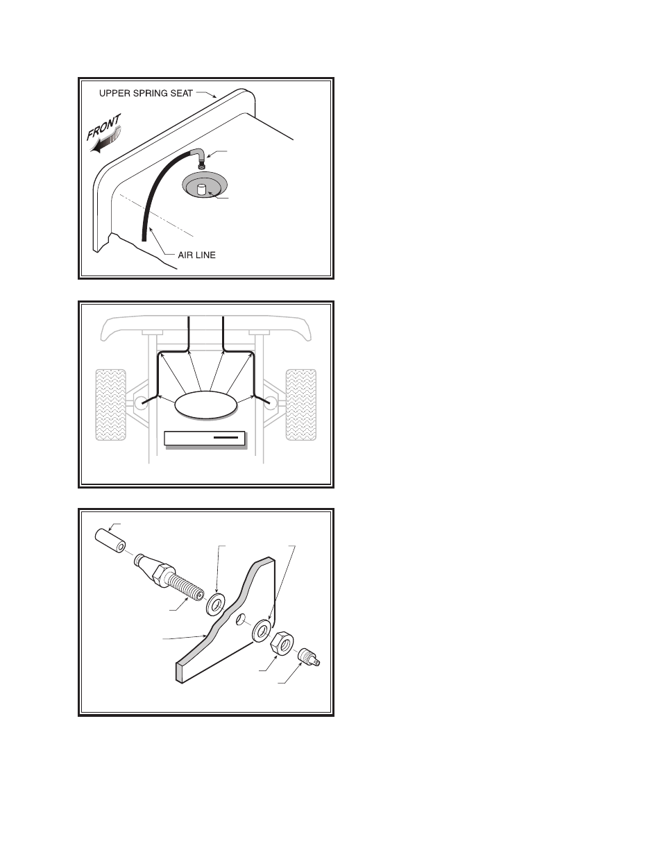
NYLON TIES
AIR LINE
AIR LINE
PUSH-TO-CONNECT
INFLATION VALVE
FLAT WASHER
HEX NUT
VALVE CAP
BODY OF
VEHICLE
Figure “F”
STEP 7 HOSE ATTACHMENT TO THE VEHICLE
With the tubing routed from the air spring to the location
of the inflation valve. Use the nylon ties supplied, secure
the air line tubing to the vehicle as shown in Figure “E”.
Be careful to avoid heat and sharp edges when fastening
the tubing to the vehicle. Stay away from the radiator and
exhaust system.
STEP 8 INSTALLING THE INFLATION VALVE
Drill a 5/16" hole where you wish to mount the inflation
valve. Remember to keep the inflation valve in a protected
area that is easily accessible. Attach the inflation valve to
the body of the vehicle as shown in Figure “F”. Tighten
all nuts at this time.
Cut the excess air line tubing so that it will fit easily
into the inflation valve, making sure the end is cut squarely
(a “saw” cut with a sharp knife is preferred). Push the end
of the tubing into the inflation valve as far as possible.
FOLLOW STEPS 2-8
FOR THE OTHER AIR SPRING.
STEP 9 INFLATE AND TEST
Inflate the air springs to recommended operating pressure
(see Page 1 for operating pressures). With a soap and
water solution, check for air leaks around the fittings and
valve core. Jack up the vehicle, remove the jack stands
and lower the vehicle to the ground. We recommend
inflating and deflating in 5 p.s.i. increments to find the
ideal riding condition for your vehicle.
NOTE:
Check air pressure on a monthly basis.
Figure “E”