Coil-rite air spring installation procedure, Warning – Rite-Ride 4102 User Manual
Page 2
COIL-RITE AIR SPRING INSTALLATION PROCEDURE
READ INSTRUCTIONS COMPLETELY BEFORE INSTALLATION.
SPRING SEAT
HEX BOLT TO
BE REMOVED
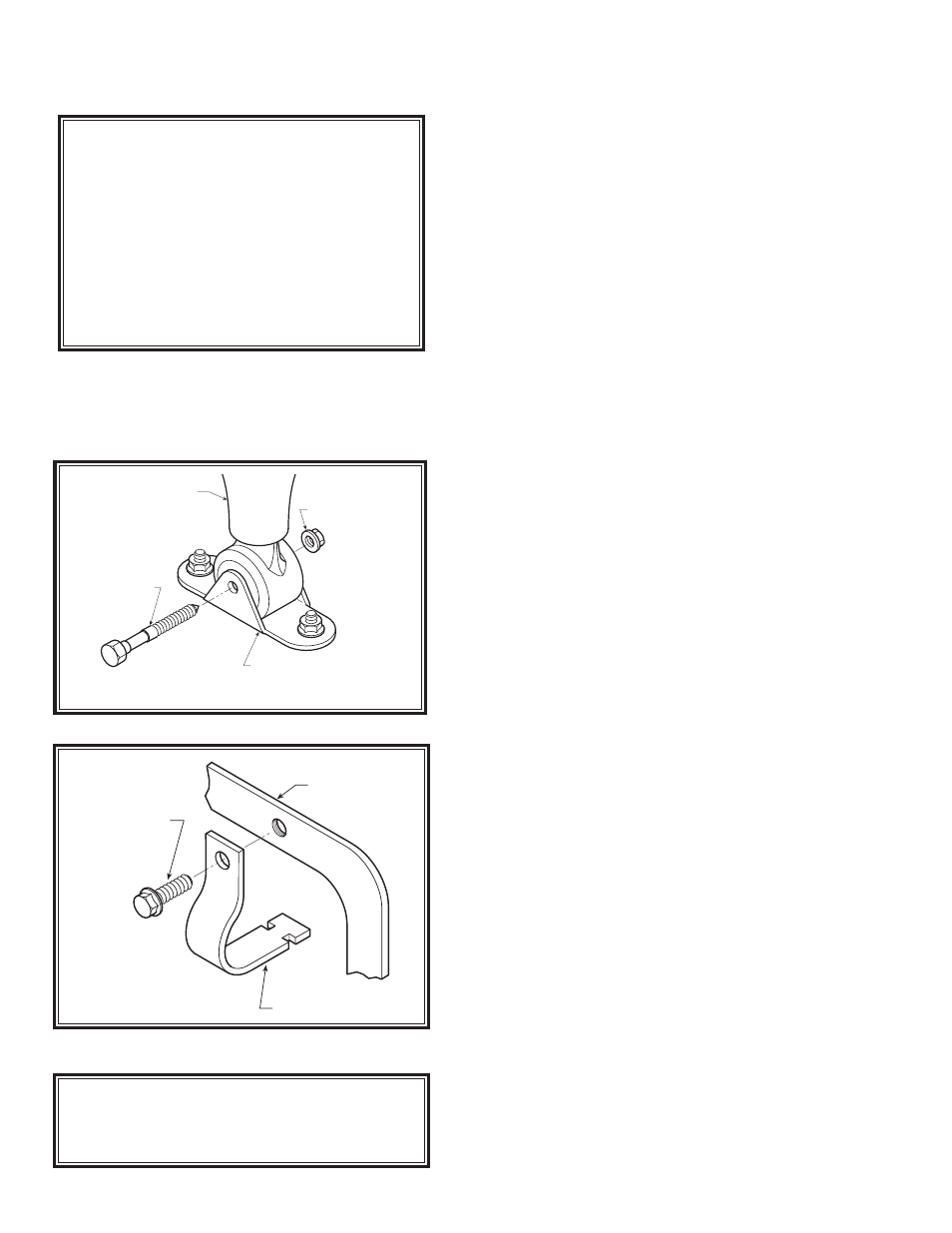
SPRING CLIP
Figure "C"
LOWER SHOCK BRACKET
SHOCK ABSORBER
HEX BOLT TO
BE REMOVED
HEX NUT TO
BE REMOVED
Figure "B"
PLEASE TAKE ALL NECESSARY SAFETY
PRECAUTIONS WHEN INSTALLING YOUR
COIL-RITE KIT.
WARNING
Do not inflate this assembly when it is
unrestricted. The assembly must be
restricted by a coil spring. Do not ever inflate
beyond recommended operating pressures
for your specific vehicle. Improper use or
over inflation may cause property damage
or severe personal injury.
FIRESTONE INDUSTRIAL PRODUCTS
CARMEL, INDIANA, USA
STEP 1 VEHICLE PREPARATION
With the vehicle on a solid level surface chock the rear
wheels. Raise the vehicle using a lift or platform jack
rated for your vehicles weight to lift the front wheels off
the ground. Remove the front wheels. Lower the vehicle
onto jack stands rated for your vehicles weight making sure
the suspension is fully extended. (Do not use wood or
concrete blocks to support the weight of the vehicle.)
STEP 2 COIL SPRING PREPARATION
Remove the lower shock absorber bolt to allow the sus-
pension to hang freely as shown in Figure “B”. The use
of a hydraulic jack placed under the axle below the coil
spring may be needed to relieve the tension on the shock.
Remove the clip holding the coil spring in the spring
seat as shown in Figure “C”. This clip is located on the
top of the coil spring and is attached to the upper coil
spring seat. Tilt the coil spring so the top of the coil spring
is exposed, see Figure “A”.
STEP 3 AIR SPRING PREPARATION
Remove one air spring from your Coil-Rite kit. Depress
the valve stem and deflate the air spring as much as pos-
sible. After deflating the air spring, roll it tightly lengthwise
and hold in that position, see Figure “A”.
STEP 4 INSTALLATION TO VEHICLE
Refer to Figure “A” throughout this step. With the valve
stem pointed up, insert the rolled-up air spring into the
top of the coil spring. Once the air spring is completely
inside the coil spring, depress the valve stem and allow
the air spring to return to its normal position.
Install the upper and lower supports as shown in
Details 1,2 and 3 on Figure “A”. Slide the lower support
through the lowest point on the coil spring and place it
over the nut and bolt on the lower spring seat or placed as
shown in Detail 3. The upper support can be placed on top
of the air spring through the open end of the coil spring.
STEP 5 RE-ASSEMBLE SUSPENSION
Place the coil spring in its original position and re-attach
the coil spring clip. Make sure the upper and lower sup-
ports have remained in the proper position. Attach the
shock absorber to the suspension. You may need to use
the hydraulic jack to raise the lower arm of the suspen-
sion. (Be sure the clip is attached and secure before
attempting this step.)
STEP 6 ROUTE THE AIR LINE
Remove the tubing from the hose kit and cut it into two
equal lengths (cut the tubing as squarely as possible).
Select a location for the inflation valves in a protected
area, such as: under the hood or on the bumper (Note:
inflation valve will be installed in Step 6). Route the air line
from the air spring to the desired location of the inflation
valve, see Figure “E”.
Attach the elbow fitting to the air spring and finger
tighten, refer to Figure “D”. Route the air line from the
air spring to the desired location of the inflation valve.
See Figure “E”.