Rite-Ride 2080 User Manual
Page 4
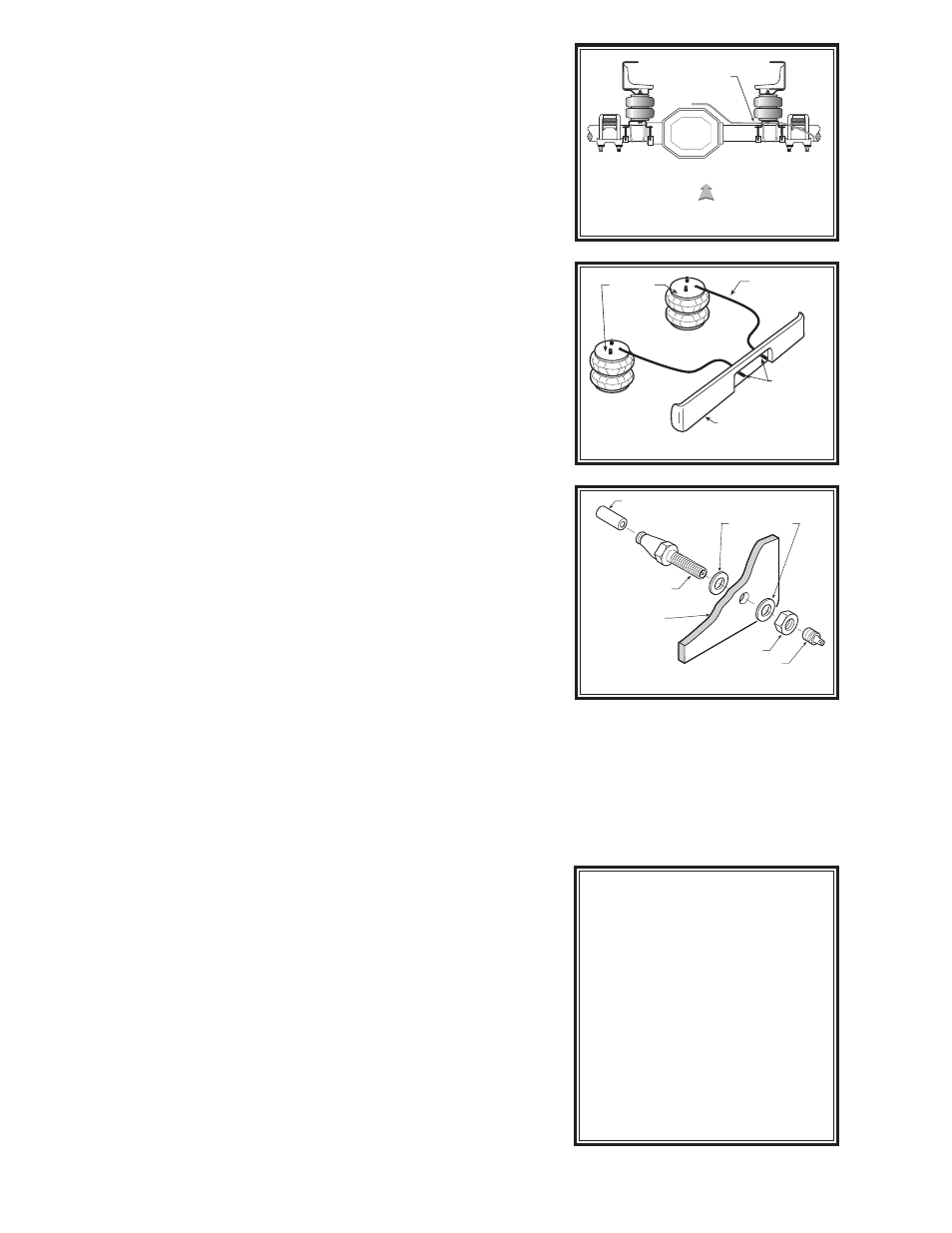
STEP 4 — INSTALL THE ASSEMBLY TO THE VEHICLE
Place the air spring assembly on top of the axle housing so that the lower
bracket straddles the shock bracket. Extend the air spring upward so
that the upper bracket is flush against the bottom of the frame rail and
the jounce bumper brace. The ribbed neck bolts in the upper bracket will
extend through the holes in the bottom of the frame rail. Install two 3/8"
-24 nylon insert lock nuts on the ribbed neck bolts and tighten them to
secure the upper bracket to the frame
see Figure “A”.
Install the axle straps necessary for your application underneath the
axle housing, aligning the ribbed neck bolts in the lower bracket with the
holes in the axle straps. Move the lower bracket inward or outward on
the axle housing as necessary to ensure that the air spring is aligned
vertically. Secure the axle straps to the lower bracket by installing four
3/8" -24 nylon insert lock nuts on the ribbed neck bolts see Figures “A”,
“D”, & “F”.
When installing the driver's side assembly, ensure that the parking
brake-line does not contact the rubber air spring. The brake-line must be
moved downward and secured to the axle or lower bracket. Use a nylon
tie to secure the parking brake-line to the lower bracket or axle see Fig-
ure “F”.
STEP 5 — INSTALL THE AIR LINE AND INFLATION VALVE
Uncoil the air tubing and cut it in two equal lengths. DO NOT FOLD OR
KINK THE TUBING. Make the cut as square as possible. Insert one end
of the tubing into the push-to-connect elbow fitting installed in the top of
the air helper spring as far as possible.
Select a location on the vehicle for the air inflation valves. The loca-
tion can be on the bumper or the body of the vehicle, as long as it is in
a protected location so the valve will not be damaged, but still maintain
accessibility for the air chuck see Figure “G”. Drill a 5/16" hole and install
the air inflation valve using two 5/16" flat washers per valve as supports
see Figure “H”. Run the tubing from the air helper spring to the valve,
routing it to avoid direct heat from the engine, exhaust pipe, and away
from sharp edges. Thermal sleeves have been provided for these condi-
tions. The air line tubing should not be bent or curved sharply as it may
buckle. Secure the tubing in place with the nylon ties provided. Push the
end of the air line tubing into the inflation valve see Figure “H”.
STEP 6 — INSTALL THE PASSENGER'S SIDE ASSEMBLY
Follow steps 2-5 for assembly and installation of the passenger’s side
assembly.
STEP 7 — CHECK THE AIR SYSTEM
Once the inflation valves are installed, inflate the air helper springs to 70
psi and check the fittings for air leaks with an applied solution of soap and
water. If a leak is detected at a tubing connection, check to make sure that
the tube is cut as squarely as possible and that it is pushed completely
into the fitting. The tubing can easily be removed from the fittings by first
releasing the pressure from the air springs, then by pushing the collar
towards the body of the fitting and then pulling out the tube. If a leak
is detected where the elbow fitting screws into the air spring, screw the
elbow into the spring until the leak stops. Reinstall the tubing and reinflate
the air springs and check for leaks as noted above.
This now completes the installation. Before proceeding, check once
again to be sure you have proper clearance around the air springs. With
a load on your vehicle and the air helper springs inflated, you must have
at least 1/2" clearance around the air springs. As a general rule, the Air
Helper Springs will support approximately 50 lbs. of load for each psi
of inflation pressure (per pair). For example, 50 psi of inflation pressure
will support a load of 2500 lbs. per pair of air helper springs. FOR BEST
RIDE use only enough air pressure in the air helper springs to level the
vehicle when viewed from the side (front to rear). This amount will vary
depending on the load, location of load, condition of existing suspension
and personal preference.
FIGURE “F”
FIGURE “G”
FIGURE “H”
AIR LINE
PUSH-TO-CONNECT
INFLATION VALVE
FLAT WASHER
HEX NUT
VALVE CAP
BODY OF
VEHICLE
AIR HOSE
INFLATION
VALVES
BUMPER
AIR
SPRINGS
DRIVER'S
SIDE
PASSENGER'S
SIDE
OFFSET
DIFFERENTIAL
FRONT
TIE PARKING
BRAKE-LINE TO
BRACKET / AXLE
NOTE:
Too much air pressure in the air
helper springs will result in a firm-
er ride, while too little air pressure
will allow the air helper spring to
bottom out over rough conditions.
Too little air pressure will also not
provide the possible improve-
ment in handling. TO PREVENT
POSSIBLE DAMAGE, MAINTAIN
A MINIMUM OF 20 P.S.I. IN THE
AIR HELPER SPRINGS AT ALL
TIMES.