Step 1— prepare the vehicle, Step 2— use of the heat shield, Step 3 — pre-assemble the kit – Rite-Ride 2080 User Manual
Page 3
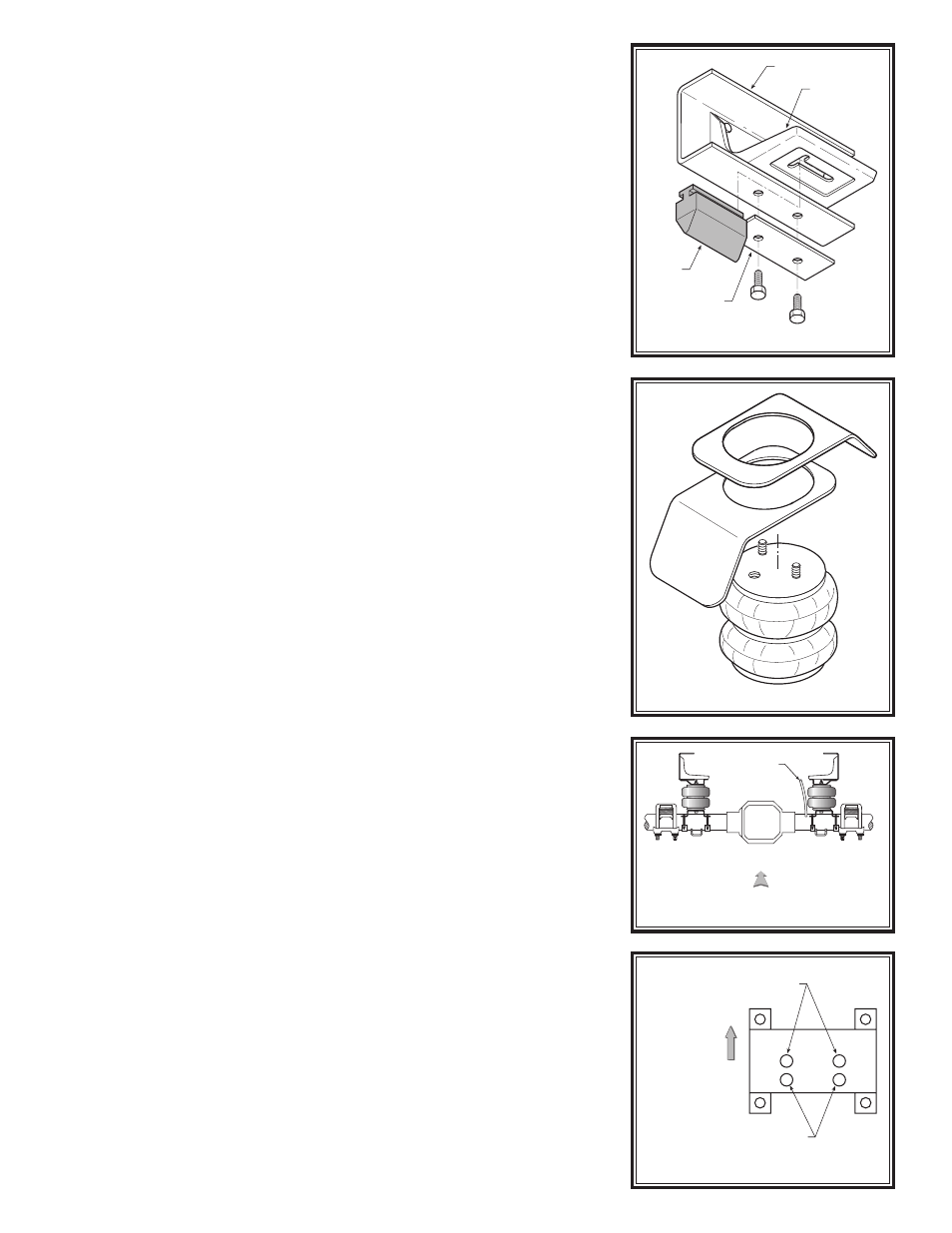
FIGURE “D”
FIGURE “C”
STEP 1— PREPARE THE VEHICLE
With the vehicle on a solid level surface, chock all four wheels and apply
the parking brake. It will not be necessary to raise the rear of the vehicle
for this installation, however, raising the vehicle may provide easier instal-
lation.
Your vehicle is equipped with rubber jounce bumpers. The bumpers
are attached to a bracket on the frame directly above the axle. Remove
these bumpers by pulling them out, while leaving the bracket intact see
Figure “B”. This bumper will not be reused with this kit.
On most vehicles, a metal plate is attached to the bottom of the frame
rail beneath the jounce bumper bracket. If your vehicle has this plate,
remove it and discard the plate and mounting bolts see Figure “B”. The
holes left in the frame from the mounting bolts will be used to attach the
upper bracket to the frame rail.
STEP 2— USE OF THE HEAT SHIELD
Note: The use of two heat shields is required on the exhaust side of
the vehicle. The heat shields will mount between the upper bracket
and the air helper spring see Figure “C”. Position the shields between
the nearest point of the exhaust pipe to the air spring. Ensure that the heat
shields will not interfere with the normal operation of the air spring or the
vehicle's suspension. Do not position the face of the shields directly over
the axle, as they may contact the axle on full suspension compression.
STEP 3 — PRE-ASSEMBLE THE KIT
Pre-assembly will begin with the left (driver's) side of the vehicle. All pic-
tures depict the installation on the left side of the vehicle unless noted
otherwise. Select one of the air springs and install the push-to-connect
air fitting in the air spring and tighten the air fitting securely to engage the
orange thread sealant. Point the air fitting so that it points toward the rear
of the vehicle and away from the exhaust pipe.
Select an upper bracket from your kit and install two 3/8" -24 x 1-1/2"
ribbed neck bolts in the bracket. Insert the ribbed neck bolts into the holes
in the upper bracket and seat them in place with a hammer see Figure
“A”. Insert the threaded studs on the air spring through the holes in the
upper bracket. The elbow fitting must be located between the tabs on the
upper bracket see Figure “A”. Secure the upper bracket to the air spring
with the provided 3/8" -16 flanged lock nuts.
A) Centered differential
On vehicles with the differential centered on the axle, the lower brackets
that are identical to each other will be used. The right-side lower bracket
will be installed on the axle closer to the outside of the vehicle to clear
the axle vent tube see Figure “D”. When attaching the right-side lower
bracket to the air spring, the holes offset to the inside of the bracket must
be used to keep the air spring in proper vertical alignment. When attach-
ing the left-side lower bracket to the air spring, use the holes centered in
the lower bracket see Figure “E”.
B) Offset differential
On vehicles with the differential offset on the axle, the dissimilar lower
brackets must be used. The air spring assembly will be installed on the
axle housing so that it straddles the shock bracket. The left-side assembly
will use the taller lower bracket and two axle straps of unequal size to
secure the lower bracket to the axle. The small axle strap will secure the
lower bracket to the axle housing while the large axle strap will secure
the lower bracket to the differential housing. The left-side assembly will
be installed so that the lower bracket straddles the shock bracket while
butting against the differential housing. The right-side assembly will be
installed with two axle straps of equal size and straddle the shock bracket
s
ee Figure “F”.
Select the proper lower bracket for your kit and install four 3/8" -24 x
2-1/2" ribbed neck bolts in the bracket. Insert the ribbed neck bolts into
the holes in the bracket and seat them in place with a hammer. Attach the
lower bracket to the air spring with two 3/8" -16 x 3/4" flanged hex bolts
see Figure “A”.
FIGURE “E”
FIGURE “B”
HEAT SHIELD
USE MARKED HOLES TO
ATTACH RIGHT-SIDE
LOWER BRACKET
OUTSIDE OF
VEHICLE
USE MARKED HOLES TO
ATTACH LEFT-SIDE
LOWER BRACKET
DRIVER'S
SIDE
PASSENGER'S
SIDE
CENTERED
DIFFERENTIAL
AXLE
VENT
TUBE
FRONT
VEHICLE
FRAME
JOUNCE
BUMPER
BRACKET
REMOVE
JOUNCE
BUMPER
REMOVE
METAL
PLATE