8 assembly, 1 assembly of housing / shaft spider, 2 assembly of slide-in unit – Richter RMI-B Series User Manual
Page 19: 3 assembly of drive unit, Assembly, Assembly of housing / shaft spider, Assembly of slide-in unit, Assembly of drive unit, Series rmi-b
Series RMI-B
close-coupled design
Page 19
9470-055-en
Revision 02
TM 8256
Edition 06/2011
7.8 Assembly
A complete assembly process is described in the
following.
Sub-sections can be deduced from this.
7.8.1 Assembly of housing / shaft spider
Push or press the shaft spider 338 into the housing
100 together with the two anti-torsion inserts
566/1.
Use a suitable plastic tube for pressing.
The pressing force must only be
applied over the sliding surface of the
shaft spider.
(risk of the silicon carbide breaking)
Insert shaft sleeve 523/1 into the shaft spider 338.
7.8.2 Assembly of slide-in unit
Press the inner magnet assembly 859 onto the
impeller 230. Pay attention to the correct alignment
of the driver cams.
Press the circlip 932/7 into the appropriate groove
on the impeller 230 with a suitable plastic tube.
Make sure that the click connection of the circlip
932/7 audibly engages to perform its function.
Press the bearing bush 545/1 into the impeller 230
together with the anti-torsion insert 566/2.
Make sure that the anti-torsion insert 566/2 is
approx. 2 mm shorter than the plain bearing.
Insert the distance ring 504/1 and then the bearing
bush 545/2.
Carefully press the thrust ring 510/2 into the
impeller 230 right to the stop. Pay attention to the
correct position of the anti-torsion insert grooves in
relation to the carrier webs in the impeller 230.
Check whether the thrust ring protrudes about 2
mm out of the impeller. See Fig. 8.
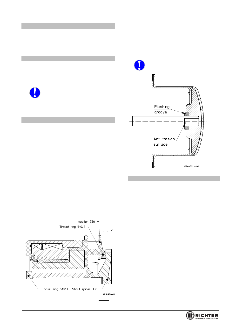
Fig. 8
Assemble can 159 and can insert 158. To
simplify assembly, the can insert 159 can be
cooled if necessary.
Introduce thrust ring 510/3 into the can insert
158. Make sure that the flushing grooves are
facing outwards.
Press shaft 222 into the can insert 158.
CAUTION: Align the shaft with the flat
pivot point in the thrust ring (risk of
the silicon carbide breaking)
Fig. 9
7.8.3 Assembly of drive unit
Affix adapter 346 to the motor flange with hex.
screws 901/7.
Check fit of the drive magnet assembly
858/hollow drive shaft 216.
Using Anti-Seize special assembly paste (e.g.
from Weicon) assemble the shaft 216 to the outer
magnet 858.
Tighten hex. socket screw 914/5 with toothed
lock washer 936/1.
Put 1 drop of adhesive on the thread of the drive
shaft, e.g. Loctite 243 from the company Loctite
(Dublin, Munich or Vienna) or an equivalent.
Only one drop of the adhesive is to be applied
per thread. Otherwise the next dismantling
operation will be more difficult or no longer
possible without destroying components.
Tightening torque group 1.1 + 1.2 = 17Nm
Tightening torque group 1.3
= 20Nm
Assemble the hollow drive shaft 216 / drive
magnet assembly 858 unit to the motor shaft.
Motors acc. IEC-standard:
After setting the “F” dimension, use a 1/4” drill bit
to drill 1 hole 1/16” deep where the set screw
contact the key. This will ensure there is no
movement of the outer drive during operation.