4 piping, 1 nominal size, 2 nozzle loads – Richter MNKA-B Series (ASME) User Manual
Page 10: 3 suction line, 4 supply lines, 5 discharge line, 6 venting and draining, Piping, Nominal size, Nozzle loads
Installation and Operating Manual
Series MNKA-B,
acc. to ASME/ANSI
9250-055-en
Revision 01
TM 5976 MPE/Wm
Page 10
Edition 10/2004
5.4 Piping
Before the pump is installed, both the suction and
supply lines as well as the discharge line are to be
cleaned.
Dirt or damage to the sealing surfaces is best avoided
if the flange covers remain on the flanges until just
before installation.
Use flange gaskets suitable for the medium.
The screw tightening torques in Section 1.2 are to be
observed for tightening the flange screws.
5.4.1 Nominal size
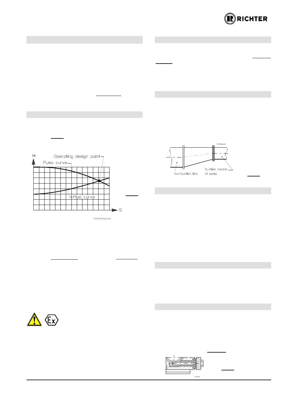
The operating design point of a centrifugal pump lies
at the intersection of the pump curve and the pipe
curve, see Fig. 2. The pump curve is provided by the
pump manufacturer. The pipe curve is determined
using diagrams or PC programs.
Under no circumstances can the nominal size of the
piping be derived from the connected nominal size of
the pump.
The pipe nominal size can also be determined using
the flow rate as a rough guide.
)
ft
(
A
x
449
)
gpm
(
Q
)
s
/
ft
(
v
2
=
)
m
(
A
)
s
/
m
(
Q
)
s
/
m
(
v
2
3
=
The velocity in the suction line should not exceed
6.56 ft/s (2 m/s) and 16.4 ft/s (5 m/s) in the discharge
line.
When determining the suction line nominal size, the
NPSH value (net positive suction head) must also be
observed. The
NPSHR value
required for the pump is
specified in the data sheet.
The NPSHR available in the plant
should be at least 1.64 ft (0,5 m)
higher than the NPSHR required for
the pump. Otherwise, this will lead to a drop in the
delivery head, cavitation or even failure of the pump.
5.4.2 Nozzle loads
The pump can be subjected to nozzle loads in
accordance with ISO
5199. See also
Product
manual
.
Changes in the length of the piping caused by
temperature are to be allowed for by appropriate
measures, e.g. the installation of expansion joints.
5.4.3 Suction line
The suction lines must always be laid on a rising
gradient towards the pump. Otherwise, gas bubbles
may form which considerably reduce the suction line
cross section. Eccentric transition elements must be
installed between different pipe diameters.
Valves which disrupt the course of flow should not be
installed directly upstream of the pump.
Fig. 3
5.4.4 Supply lines
Supply lines should vent towards the reservoir and are
therefore to be laid with a constant downward gradient
towards the pump. Should the piping internals
upstream of the pump be horizontal, a low point can,
of course, be located upstream of these internals.
From here the pipe is then laid with an upward
gradient to the pump so that the gas bubbles which
form here can escape through the pump.
Valves which disrupt the course of flow should not be
installed directly upstream of the pump.
5.4.5 Discharge line
Do not arrange the shut-off valve directly above the
pump but initially provide a transition section.
The discharge nozzle velocity of the medium can – if
necessary – be reduced.
5.4.6 Venting and draining
Venting can take place into the discharge line or
upstream of the discharge valve.
A venting line can also be used as a bypass, drain or
flushing line.
The pump housing (casing) is fitted with a drain
connection as a standard feature. Optionally, the drain
bore can be drilled. See
Figure 4
.
Fig. 2
Fig. 4