5 pipe fittings, 6 monitoring facilities, 7 drive – Richter MNK Series User Manual
Page 12: 8 coupling, Pipe fittings, Monitoring facilities, Drive, Coupling, Series mnk
Series MNK
Page 12
9230-050-en
Revision 11
TM 7903
Edition 07/2010
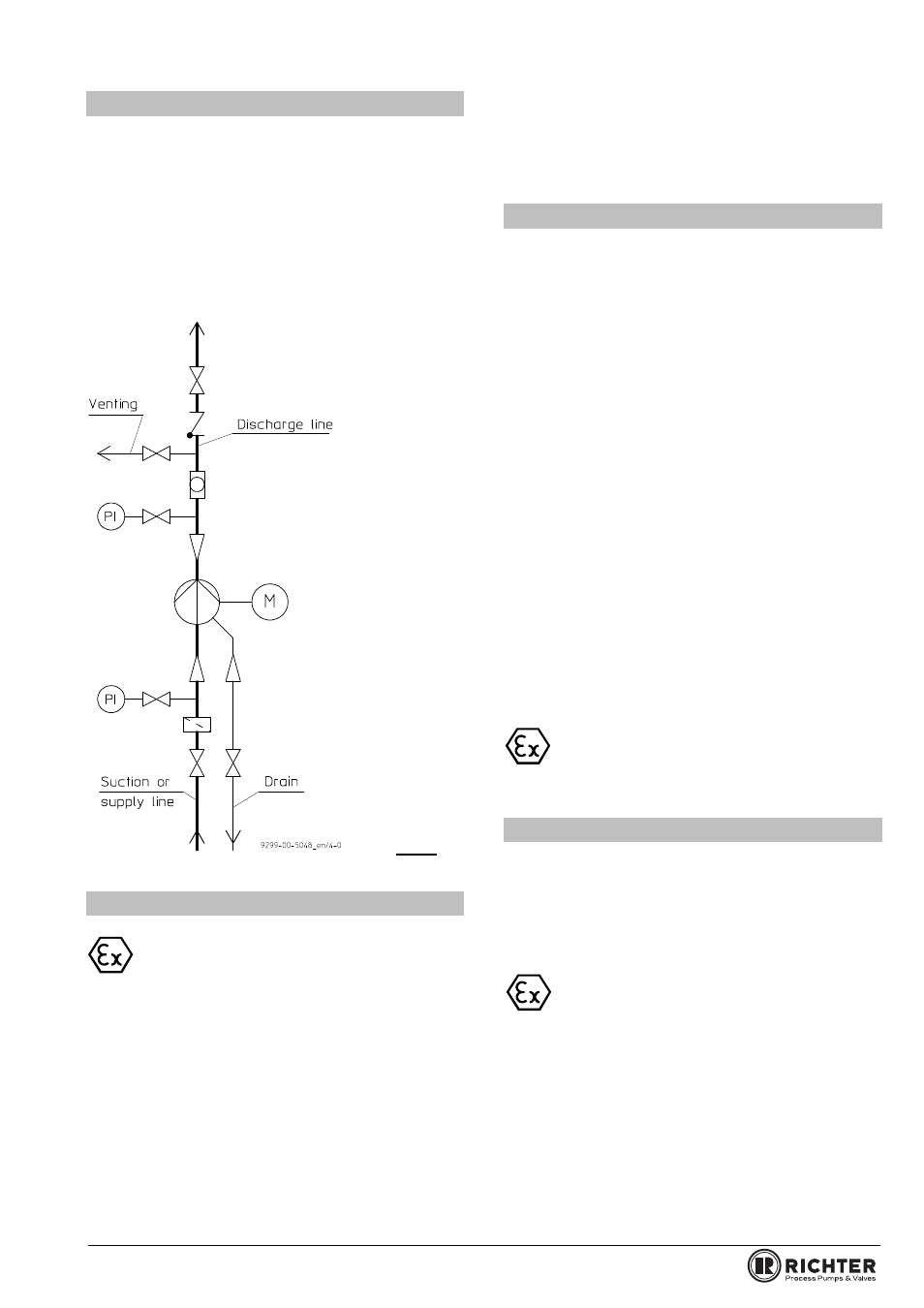
5.5 Pipe fittings
The following pipe fittings are available from Richter
on request:
Shut-off valves
Check valves
Sight glasses
Priming vessels
Strainers
Pressure gauges
Fig. 5
5.6 Monitoring facilities
Appropriate monitoring facilities are to be
recommended, depending on the require-
ments placed on operational safety and
availability of the unit.
Richter provides information on request and can
supply:
Flow meters
Filling level indicators
Motor load monitors
Temperature monitors
Rolling bearing monitors
Can monitors
Leak monitors
SAFERUN
®
Condition Monitoring System
You can obtain the publications "Safe Operation of
Magnetic drive Pumps" and "The Operation of
Centrifugal Pumps without NPSH Problems" on
request.
5.7 Drive
The power consumption of the pump at the operating
design point is specified in the data sheet and works
certificate. If the operating design point was not known
when the pump was dispatched, the power
consumption can be read off the appropriate
performance curves. The max. density, the max.
viscosity and a safety margin are to be allowed for.
Care must be taken when selecting the motor size to
ensure that the excess power is not too great. During
start-up the magnetic drive could otherwise stop.
The magnetic drive rating at the nominal speed of
2900 rpm is given in the pump data sheet.
If the motor rating exceeds this magnetic drive rating –
at pump speed -, it is necessary to check for any
stoppage of the magnetic drive.
This also applies if the required drive rating exceeds
80% of the magnetic drive rating – at pump speed.
Consult Richter if necessary.
Different operating data can be achieved without
changing the pump through the use of different
speeds, e.g. by means of a frequency converter.
The pump with base plate and motor is illustrated in
the
installation drawing
.
The
operating manual of the motor manufacturer
must be observed.
A motor with a valid ATEX certificate is to be
used if employed in zone 1 and 2.
5.8 Coupling
If one coupling half engages with the other, the claw
section is normally to be mounted on the pump shaft
and the coupling half with the smooth end face on the
motor shaft.
Observe the operating manual of the coupling
manufacturer.
A coupling with a valid ATEX certificate is to
be used if deployed in zone 1 and 2.
Regulations exist, e.g. for the following details:
Arrangement of the coupling halves
Max. bore diameter
Max. transmitted power
Spacing of the coupling halves
Maximum values for offset and angular misalignment.
Should the pump housing and motor remain on the
base plate for repair work, a spacer type coupling is
required.