Kenco Engineering KPS User Manual
Page 3
OIL LEVEL CONTROLLER WITH
–17
(Waukesha VHP Engines F2895, F3251, F5108, L5790 & L7042),
-18
(-17 w/ meter),
-27
(for newer Waukesha engines same as –17),
–37
(Waukesha P9390),
-38
(same as –37 w/ meter) AND –FS OPTIONS
•
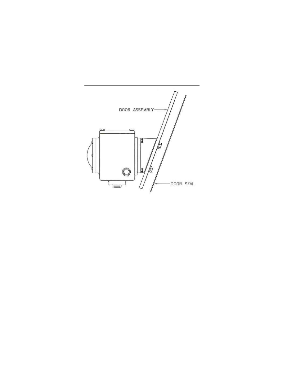
Remove the cast aluminum inspection door from the engine. Remove the clamp bar from the old door.
•
For –17, -18, -37, -38 install the o-ring into the groove of the Kenco door and replace the clamp bar on the back side of the door
using the 5/8” bolts, washers, and o-rings supplied by Kenco.
•
For –27, install the o-ring into the groove of the Kenco door and replace the clamp bar on the back side of the door using the
7/16” bolts and the stat-o-seals supplied by Kenco.
•
Install the equalizing line between the controller cover plate and the door (Tubing and connectors supplied by Kenco).
•
Place the controller assembly into the inspection port of the engine and tighten the center bolt(s) down.
•
Install oil inlet line into the controller oil valve or the meter inlet port.
•
NOTE: For the –18 model, refer to the additional instructions supplied with the 1618 Kenco Low Flow meter.
Figure 4: -Door Assembly for –17, -18, -27, -37, -38
OIL LEVEL CONTROLLER WITH
-24
(Ariel Compressor JGB, JGE, JGH, JGK, JGR, JGT, JGV, & JGW) and
-48
(Ariel compressor JGC & JGD) AND –FS OPTIONS
•
Remove the sight glass located on the crankcase and replace it with the oil controller assembly using the mounting bolts and
gasket supplied with the unit.
OIL LEVEL CONTROLLERS WITH
–1
(Clark MA & CFA)
–2
(Clark HMB & TMB),
-3
(Clark RA, HRA, HBA, HCA, HLA,
TLA),
-6
(Cooper-Bessemer GMW),
-7
(Cooper-Bessemer GMV),
-8
(Cooper-Bessemer GMX),
-16 , -16-R, -16-6.25
(Cooper-
Bessemer BMV & 275) AND FS OPTIONS
•
Remove the visual oil gauge assembly from the engine and replace it with the oil level controller and adapter assembly supplied
with a gasket and mounting bolts when applicable.
OIL LEVEL CONTROLLERS WITH
–4
(Ingersoll-Rand SVG & KVS),
-5
(Ingersoll-Rand KVG) AND FS OPTIONS
•
Remove the visual oil gauge assembly from the engine and replace it with the oil level controller and adapter assembly supplied
with a gasket and mounting bolts when applicable.
•
If an equalizing exists for the engine sight glass and detach the equalizing line from the sight glass while still attached to the
engine.
•
Install the oil controller and then reattach the equalizing line to the vent located at the top of the adapter.
Note: It is important to insure that there are no loops in this line for it must be trap free and self draining.