Kenco Engineering K9900 Series Level Gauge User Manual
Page 2
D. Carefully Lower Sight Tube Out Of Block In Upper End Of Gauge Frame.
Note: If Sight Tube Has A Splicer, Extra Care Should Be Taken So Sight Tube Assembly Does Not Disassemble.
E. Remove O-Ring Compression Plates And Seals From Sight Tube.
5. Installation Of Sight Tube Is As Follows:
A. Insert Sight Tube Into Splicer If One Exists. If A Teflon Shrink-Tube Type Splicer Exists, It Will Be Necessary To Place Teflon
O-Ring Cushion Between Adjoining Sight Tubes And Heat-Shrink Teflon Splicer In Place.
B. Slide 1-3/8” Square X 1/4” Thick O-Ring Compression Plate Onto Each End Of Sight Tube.
C. Slide O-Ring Seal Onto Each End Of Sight Tube.
D. Push End Of Sight Tube Into Hole In Block Inside Frame On Upper End Of Gauge As Far As Is Required To Enable Lower End
Of Sight Tube To Swing Over And Into Hole In Block Inside Frame On Lower End Of Gauge..
Note: On Very Short Gauges, It May Be Necessary To Remove Sight Tube Through 1/2” FNPT Vent Port On Upper End Of Gauge.
E. Install Hex Socket Head Cap Screws Into Blocks On Each End Of Gauge And Thread Into Holes In 1-3/8” Square X 1/4” Thick
O-Ring Compression Plates And Tighten Securely.
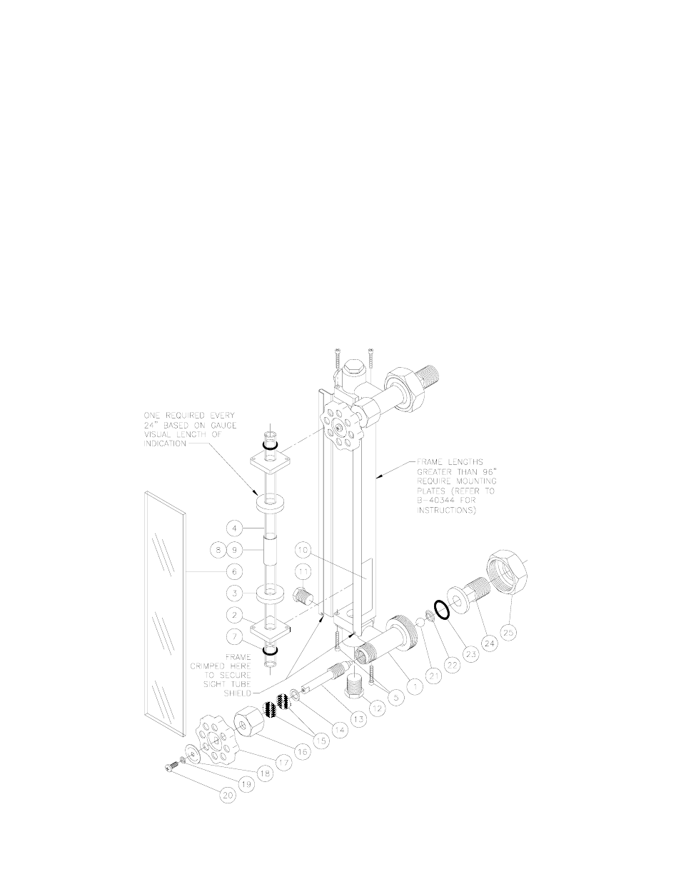
6. Integral Valve Stem Contained On Each End Of Gauge To Be Assembled And Disassembled As Illustrated In Exploded View Below
(Note: When Reassembling Valves Bodies, We Recommend Using A Lubricating Compound On Threads To Protect Against Corrosion,
Seizure, Galling, Rust, Carbon Fusion, Etc.)